
Decoding the Standard Wiring Diagram for a 5 Pin Trailer Plug
The 5-pin flat connector is the undisputed workhorse for boat trailers, motorcycle carriers, and light utility rigs. When you first examine the standard wiring diagram for a 5 pin trailer plug, it looks nearly identical to the ubiquitous 4-way flat connector, with one critical addition: a fifth wire (typically blue) dedicated to auxiliary functions. In 90% of recreational applications, this fifth pin triggers a reverse lockout solenoid, which disengages the trailer's surge brakes when the tow vehicle shifts into reverse. In rare commercial applications, it may serve as an electric brake controller feed or auxiliary power source.
However, having the correct diagram is only half the battle. Environmental exposure, vibration, and varying electrical loads mean that physical wiring rarely matches the theoretical diagram perfectly over time. This inspection and testing guide will walk you through verifying your trailer's electrical integrity using professional diagnostic methods.
Pro Tip: Never rely solely on a visual 'bulb check' to verify trailer wiring. A corroded socket can create a high-resistance connection that lights a bulb dimly but will fail under the sustained amperage draw of a long highway drive, potentially melting the harness.
Standard 5-Pin Flat Pinout Matrix
| Pin Position | Standard Wire Color | Circuit Function | Expected Voltage (Engine On) | Typical Amperage Draw |
|---|---|---|---|---|
| 1 (Left Outer) | White | Ground (Chassis) | 0.0V (Continuity to Ground) | N/A (Return Path) |
| 2 (Left Inner) | Brown | Tail / Running Lights | 12.5V - 13.8V DC | 0.5A - 1.5A (Total) |
| 3 (Center) | Yellow | Left Turn / Stop | 12.5V - 13.8V DC (Pulsed) | 2.1A per bulb |
| 4 (Right Inner) | Green | Right Turn / Stop | 12.5V - 13.8V DC (Pulsed) | 2.1A per bulb |
| 5 (Right Outer) | Blue | Reverse Lockout / Aux | 12.5V - 13.8V DC (Reverse Only) | 8.0A - 12.0A (Solenoid Spike) |
Phase 1: Pre-Test Visual Inspection Protocol
Before connecting any testing equipment, perform a rigorous physical inspection. According to eTrailer's comprehensive wiring FAQ, over 75% of trailer lighting failures stem from physical connector degradation rather than broken wires inside the loom.
- Pin Spread Check: Inspect the male pins on the tow vehicle side and the female slots on the trailer side. 'Pin spread' occurs when a pin is pushed backward into the rubber housing upon insertion, preventing contact. Use a small flathead screwdriver to gently reseat any recessed pins.
- Corrosion Mapping: Look for green or white copper oxide buildup. Surface corrosion on the pins can be cleaned with fine-grit sandpaper (400-grit), but if corrosion has wicked up inside the wire insulation capillary, the wire must be cut back and re-terminated.
- Dielectric Grease Application: Once cleaned, apply a generous coat of Permatex 22058 Dielectric Tune-Up Grease (approx. $6 per tube) to the pins. This displaces moisture and prevents galvanic corrosion between dissimilar metals (e.g., brass pins and aluminum trailer frames).
Phase 2: Multimeter Testing Procedures
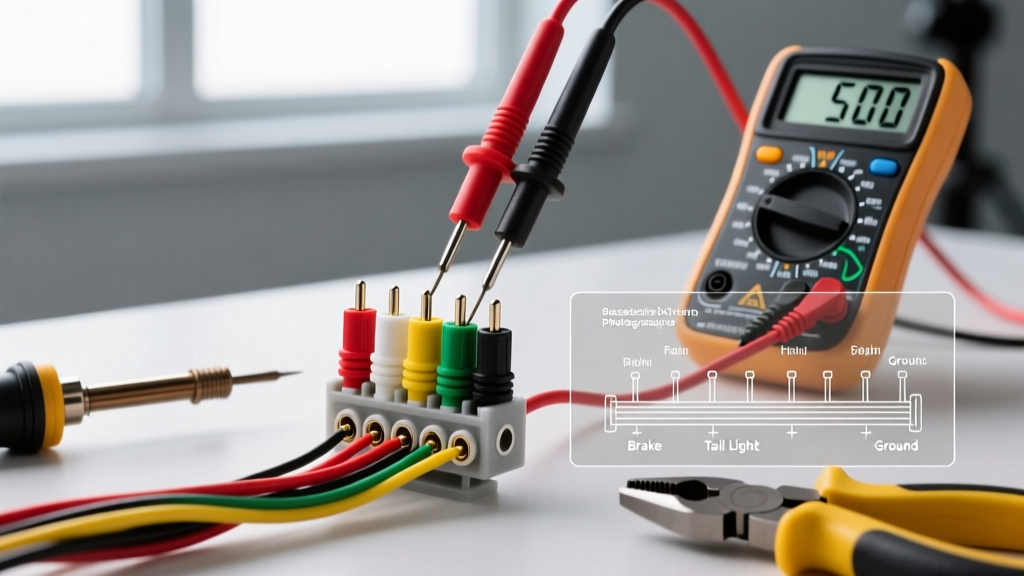
Ditch the cheap incandescent test lights. To properly verify your wiring diagram for a 5 pin trailer plug, you need a Digital Multimeter (DMM) capable of measuring DC voltage and continuity, such as the Fluke 117 True RMS Multimeter (approx. $210) or the budget-friendly Klein Tools MM400 (approx. $45).
Step 1: Ground Continuity and Voltage Drop
The white wire (Pin 1) is the most common point of failure. A poor ground will cause 'backfeed,' where applying the brakes causes the tail lights to illuminate, or turning left causes the right marker light to flash.
- Set your DMM to the Ohms/Continuity setting.
- Place the black probe on a known clean, bare metal point on the tow vehicle's chassis.
- Place the red probe on Pin 1 (White) of the trailer plug.
- You should see a resistance reading of less than 0.5 ohms. If your DMM beeps, continuity is confirmed. For a deeper dive on testing techniques, refer to Fluke's official continuity testing guide.
- Voltage Drop Test: Switch the DMM to DC Volts. With all trailer running lights turned ON, place the red probe on the trailer frame and the black probe on the tow vehicle's negative battery terminal. A reading above 0.2V indicates a severely compromised ground path that requires cleaning or running a dedicated 10 AWG ground wire directly to the trailer tongue.
Step 2: Load Testing the Lighting Circuits
Test Pins 2, 3, and 4 (Brown, Yellow, Green) with the tow vehicle running to ensure the alternator is supplying a steady 13.2V to 13.8V. Have an assistant press the brake pedal and activate the turn signals. Watch the DMM display; voltage should not dip below 11.5V under load. If it does, you have undersized wiring or a corroded splice in the tow vehicle's harness.
Step 3: Isolating the 5th Pin (Blue Wire)
Shift the tow vehicle into Reverse (with the parking brake firmly engaged and wheels chocked). Probe Pin 5. You should read full battery voltage. Warning: Reverse lockout solenoids on boat trailers draw a massive initial inrush current (often 10 to 15 amps). If your tow vehicle's reverse light circuit is not rated for this amperage, it will blow the vehicle's fuse immediately. In such cases, you must wire the 5th pin through a dedicated 20A relay triggered by the reverse light circuit, rather than drawing power directly through the plug.
Advanced Troubleshooting Matrix: Symptoms vs. Root Causes
| Observed Symptom | Probable Root Cause | Diagnostic Fix |
|---|---|---|
| Brakes cause tail lights to glow | Backfeed due to missing or corroded ground (White wire) | Clean ground stud on trailer tongue; verify continuity to vehicle chassis. |
| Right turn signal hyper-flashes | Burnt bulb, or LED conversion without load resistors | Check bulb filament; if LED, install 6-ohm load resistors in parallel. |
| Blown fuse when shifting to Reverse | 5th pin solenoid drawing more current than tow vehicle reverse circuit | Install a 12V 30A automotive relay; use reverse light as trigger only. |
| Running lights flicker over bumps | Pin spread on Pin 2 (Brown) or loose crimp at trailer tongue | Re-tension female connector slots; heat-shrink solder all tongue splices. |
The 2026 Edge Case: CAN-Bus Systems and LED Conversions
Modern tow vehicles (2020 through 2026 models from Ford, GM, and Toyota) utilize sophisticated Body Control Modules (BCMs) with CAN-bus networking. These systems actively monitor the current draw of the trailer lighting circuits to detect burnt-out bulbs.
If you upgrade your trailer to LED lighting—which draws roughly 0.25 amps per fixture compared to the 2.1 amps of traditional 1157 incandescent bulbs—the BCM may interpret the low amperage as a 'burnt bulb' or a 'short circuit.' Consequently, the BCM will cut power to the circuit entirely, leaving you with dark trailer lights despite perfect wiring continuity.
The Solution: Do not rely on cheap inline resistors that generate excessive heat and can melt plastic housings. Instead, install a smart solid-state flasher relay (like the Tow Ready 20157) or use LED-specific trailer harness adapters equipped with integrated PWM (Pulse Width Modulation) bypass modules. These devices simulate the electrical load of incandescent bulbs, tricking the BCM into maintaining a steady 13.8V output.
Final Inspection Sign-Off
Verifying a wiring diagram for a 5 pin trailer plug is not a 'set it and forget it' task. The harsh realities of road salt, boat ramp submersion, and highway vibration demand a proactive testing schedule. By combining a rigorous visual inspection with precise multimeter load testing, you ensure that your trailer remains legally compliant and, more importantly, safe for the motorists sharing the road behind you. Always keep a spare 5-way flat connector and a crimping tool in your tow rig's glovebox—because on the road, a reliable electrical connection is your only guarantee of visibility.