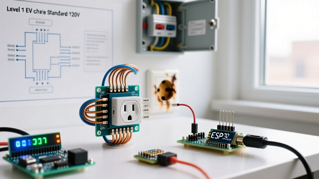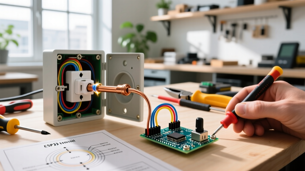

Why Did Your Outlet Suddenly Die?
When you plug in a device and nothing happens, it is easy to assume the worst. However, understanding exactly what to do when electrical outlet stops working requires a systematic, safety-first approach rather than guesswork. According to the National Fire Protection Association (NFPA), electrical failures or malfunctions are a leading cause of home fires, often stemming from loose connections, degraded receptacles, or overloaded circuits. Before you rip open your walls or call an electrician for a $150 to $300 service call, you can diagnose and often fix a dead receptacle yourself.
This guide walks you through a professional-grade, step-by-step diagnostic and installation process to isolate the failure mode, test the circuit, and safely replace a faulty 15A or 20A duplex receptacle.
Phase 1: Non-Invasive Diagnostics (No Tools Required)
Before unscrewing a single faceplate, you must rule out upstream interruptions. Over 60% of "dead" outlets are actually victims of a tripped protective device elsewhere in the home.
1. Hunt for Upstream GFCI and AFCI Trips
Modern electrical codes require Ground Fault Circuit Interrupter (GFCI) protection in wet areas (kitchens, bathrooms, garages, exteriors) and Arc Fault Circuit Interrupter (AFCI) protection in living spaces. These devices are highly sensitive and will cut power to all downstream "daisy-chained" outlets if they detect a micro-amp leakage or an arc signature.
- The Kitchen/Bathroom Sweep: Check every GFCI receptacle in the room and adjacent rooms. Press the "TEST" button, then press "RESET" firmly until it clicks. A tripped GFCI (like the common Leviton 8599-W) will have a popped-out reset button.
- The Breaker Panel Check: Locate your main service panel. Look for a breaker that is in the "TRIP" position (often resting in the middle, between ON and OFF). To reset it, you must push it fully to the OFF position until it clicks, then flip it to ON. If it immediately trips again, you have a hard short circuit—stop and proceed to Phase 2.
Phase 2: Voltage Testing and Isolation
If the breakers are on and GFCIs are reset, the issue is localized to the outlet or the wiring feeding it. You need a Non-Contact Voltage Tester (NCVT) and a Digital Multimeter (DMM). We recommend a True-RMS meter like the Fluke 117 (approx. $190) or a budget-friendly Klein Tools MM400 (approx. $45) to avoid false readings from "phantom voltage" induced by adjacent live wires.
The Receptacle Diagnostic Matrix
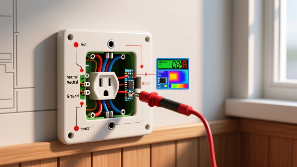
Set your DMM to VAC (Volts Alternating Current) and insert the probes into the outlet slots. Use this matrix to interpret your findings:
| Test Points | Expected Reading | Actual Reading | Diagnosis & Failure Mode |
|---|---|---|---|
| Hot to Neutral (Short slot to Long slot) | 115V - 125V | 0V | Open Hot or Open Neutral. Power is not reaching the receptacle, or the internal brass/silver contacts have failed. |
| Hot to Ground (Short slot to U-shape) | 115V - 125V | 120V (but H-N is 0V) | Open Neutral. The hot wire is live, but the neutral path is broken. Check for a disconnected white wire in the back of the box. |
| Neutral to Ground (Long slot to U-shape) | 0V - 2V | 120V | Reverse Polarity or Open Ground with a load. Extremely dangerous; the neutral is carrying current but is disconnected from the panel. |
Phase 3: The Tear-Down and Physical Inspection
Once your DMM confirms 0V across Hot-Neutral and Hot-Ground, it is time to open the receptacle. Safety is paramount here. The U.S. Consumer Product Safety Commission (CPSC) strongly advises turning off the main breaker or the specific branch circuit breaker before touching any bare wires.
- Kill the Power: Turn off the branch circuit breaker. Verify it is dead by testing the outlet again with your NCVT and DMM.
- Remove the Faceplate: Use a #1 Phillips or flathead screwdriver to remove the center screw holding the cover plate.
- Extract the Receptacle: Remove the top and bottom 6-32 mounting screws securing the yoke (metal strap) to the electrical box. Gently pull the receptacle out, being careful not to touch the side terminal screws.
Identifying the "Backstab" Failure Mode
Look at the back of the old receptacle. Are the wires inserted into small holes in the plastic back? These are "push-in" or "backstab" connections. They rely on a tiny internal brass spring clip to grip the 14 AWG or 12 AWG copper wire. Over years of thermal cycling (heating up under load and cooling down), these springs lose tension, leading to high-resistance connections, arcing, and eventual failure. If your dead outlet was backstabbed, this is almost certainly your culprit.
Phase 4: Step-by-Step Receptacle Replacement
If the receptacle is physically degraded, burnt, or relies on backstabbed connections, it must be replaced. A standard 15A duplex receptacle (like the Leviton 5320-WCP) costs about $3.50, while a commercial-spec grade version (Leviton 5320-E) costs around $5.50 and offers superior internal grip.
Wiring the New Receptacle Correctly
Never reuse backstab connections. Always use the side terminal screws for a secure, long-lasting mechanical bond.
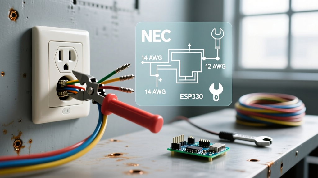
- Strip the Wires: If the old wire ends are pitted or bent, cut them back and use your wire strippers to expose exactly 3/4 inch of fresh copper. Most modern receptacles have a "strip gauge" printed on the back to guide you.
- Form the J-Hook: Use the tip of your lineman's pliers or a dedicated wire-loop tool to bend the exposed copper into a tight "J" shape or shepherd's hook.
- Connect the Ground (Green Screw): Loop the bare copper or green insulated wire clockwise around the green grounding screw. Tighten until the loop closes flat against the yoke.
- Connect the Neutral (Silver Screw): Loop the white neutral wire clockwise around the silver terminal screw. The clockwise orientation ensures that tightening the screw pulls the loop tighter rather than pushing it out.
- Connect the Hot (Brass Screw): Loop the black hot wire clockwise around the brass terminal screw.
Expert Torque Tip: While the National Electrical Code (NEC) Article 110.14(D) mandates specific torque values for terminations, most standard 15A/20A residential receptacles require approximately 12 to 14 inch-pounds of torque. If you do not have a torque screwdriver, tighten the screw until it is firmly snug and the wire loop cannot be moved by hand. Do not overtighten, as you can strip the brass threads on cheap receptacles.
Handling Downstream (Daisy-Chain) Wiring
If your electrical box has two sets of cables (two blacks, two whites, two grounds), this outlet is feeding power to downstream outlets. You must connect both black wires to the brass side, both white wires to the silver side, and all ground wires together. The safest method is to use a wire nut (or Wago 221-413 lever connector) to pigtail the two wires together with a short 6-inch jumper wire that connects to the single terminal screw on the receptacle. This prevents breaking the circuit if the receptacle is ever removed in the future.
Phase 5: Reassembly and Final Verification
Once the wires are securely terminated, carefully fold them into the back of the electrical box. Push the receptacle in, ensuring no bare ground wires are touching the brass or silver terminal screws (a common cause of immediate breaker trips upon reassembly).
- Secure the yoke to the box using the provided 6-32 screws. Use a torpedo level to ensure the receptacle sits perfectly plumb before fully tightening.
- Reattach the faceplate.
- Restore power at the breaker panel.
- Test the outlet with a simple plug-in circuit tester (like the Sperry Instruments GFI-350A, approx. $12) to verify correct wiring, or re-test with your DMM to confirm 120V across Hot-Neutral.
When to Call a Licensed Electrician
While replacing a standard receptacle is a straightforward DIY task, certain scenarios require professional intervention. If your DMM reads 0V at the receptacle, but the wires entering the back of the box also read 0V when tested directly, the break in the circuit is hidden inside your walls. This could be a severed cable from a rogue drywall nail, a completely melted wire nut in a junction box, or rodent damage. Furthermore, if you open the box and discover aluminum wiring (identifiable by its silver color and "AL" stamping on the wire jacket), stop immediately. The National Electrical Code (NEC) requires specific CO/ALR rated devices and specialized anti-oxidant paste for aluminum terminations to prevent catastrophic fires. In these edge cases, troubleshooting what to do when electrical outlet stops working transitions from a DIY repair to a job for a licensed master electrician.