
The Hidden Risks of Extending a Circuit
When homeowners decide to extend an electrical outlet to power a new workspace, wall-mounted TV, or smart home hub, the physical act of running wire is only half the battle. The true danger lies in what happens behind the drywall at the donor receptacle. Failing to properly inspect and test the existing circuit before adding a new load is a primary cause of residential electrical fires. According to the U.S. Consumer Product Safety Commission (CPSC), electrical receptacles and branch circuit overloads account for thousands of structural fires annually.
As of 2026, with the proliferation of high-draw smart appliances, continuous-load EV trickle chargers, and space heaters, circuits are under more stress than ever. This inspection and testing guide will walk you through the exact diagnostic protocols professional electricians use before they ever cut a hole in the wall to extend an electrical outlet.
Phase 1: Circuit Load and Capacity Testing
Before you extend an electrical outlet, you must verify that the donor circuit has the available amperage to handle the new load. The National Electrical Code (NEC) mandates that continuous loads (those expected to run for three hours or more) must not exceed 80% of the breaker's rating.
Measuring Real-Time Draw
Do not rely on guesswork or simply adding up the wattage labels on your devices. You must measure the actual, real-time current draw of the circuit.
- Acquire a True-RMS Clamp Meter: A standard multimeter will not work here. You need a clamp meter (such as the Fluke 323 or Klein CL800) capable of measuring AC current without breaking the circuit.
- Isolate the Hot Conductor: At the breaker panel, safely isolate the single hot wire feeding the donor circuit. (Note: Clamping over both the hot and neutral wires simultaneously will read zero due to magnetic field cancellation).
- Establish a Baseline: Turn on all existing devices plugged into the donor circuit. Record the baseline amperage.
- Calculate Headroom: A standard 15-amp breaker should not see a continuous load above 12 amps (1440 watts). A 20-amp breaker is capped at 16 amps continuous (1920 watts). If your baseline is already at 11 amps on a 15-amp circuit, you cannot safely extend an electrical outlet for a new continuous load.
Pro Tip: If the donor circuit is a 15-amp breaker wired with 14 AWG copper, you are strictly limited to 15 amps total. If you find 12 AWG wire on a 15-amp breaker, do not assume you can swap to a 20-amp breaker. The entire circuit, including every downstream receptacle and switch, must be rated for 20 amps and utilize 12 AWG wire.
Phase 2: Box Fill Inspection (NEC Article 314.16)
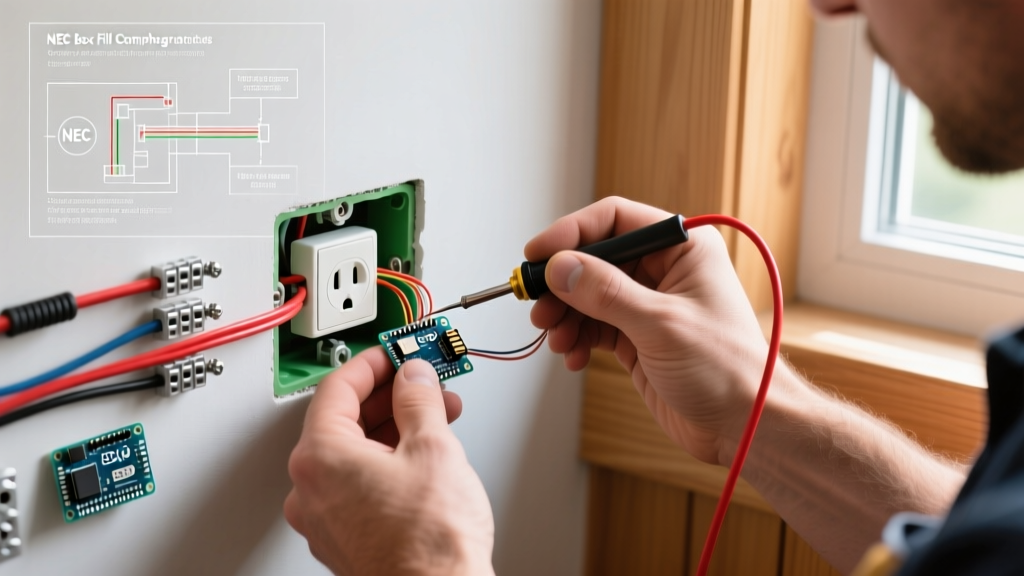
The most frequently violated code when attempting to extend an electrical outlet is box fill capacity. Every electrical box has a maximum cubic inch volume. Every wire, clamp, and device strap takes up a specific amount of that volume. Cramming too many wires into a shallow box causes heat buildup and physical damage to wire insulation.
Under the National Fire Protection Association (NFPA) NEC guidelines, you must calculate the box fill before adding new pigtails or pass-through wires.
Calculating Your Donor Box Volume
First, determine the cubic inch capacity of the existing donor box. Plastic boxes usually have this stamped on the inside (e.g., '18 CU IN'). Steel boxes require measurement or referencing a manufacturer chart.
| Conductor Size | Volume Allowance per Wire | Device (Receptacle) Allowance | Internal Clamp Allowance |
|---|---|---|---|
| 14 AWG | 2.0 cubic inches | 4.0 cubic inches | 2.0 cubic inches |
| 12 AWG | 2.25 cubic inches | 4.5 cubic inches | 2.25 cubic inches |
| 10 AWG | 2.5 cubic inches | 5.0 cubic inches | 2.5 cubic inches |
Example Calculation: Imagine a standard 18-cubic-inch plastic box housing a single 12 AWG duplex receptacle. Currently, it has one 12/2 cable entering (1 hot, 1 neutral, 1 ground).
- 1 Hot wire = 2.25 cu in
- 1 Neutral wire = 2.25 cu in
- 1 Ground wire (all grounds count as 1) = 2.25 cu in
- 1 Receptacle device = 4.5 cu in
- Total Existing Fill: 11.25 cubic inches.
If you extend an electrical outlet from this box, you will add a second 12/2 cable (1 hot, 1 neutral, 1 ground) and two new wire nuts. The new wires add 6.75 cubic inches. The new total is 18.0 cubic inches. You have exactly maxed out the box. If the existing box was only 14 cubic inches, you would be in direct violation of the NEC and must upgrade to a deeper box, such as the Carlon B618R (18 cu in) or B625R (25.5 cu in) before proceeding.
Phase 3: Donor Receptacle and Wiring Inspection
Once capacity is verified, physically inspect the donor receptacle. The condition of the existing termination dictates how you will make your extension.
Identifying Push-In Backstabs
Look at the back of the existing receptacle. Are the wires inserted into small holes using the internal spring clips (backstabs)? You cannot safely extend an electrical outlet using backstabbed connections. These spring-loaded connections are notorious for loosening over time, leading to high-resistance arcing. If the donor receptacle is backstabbed, you must remove the wires, strip them back to fresh copper, and pigtail them using the side-screw terminals or approved push-in connectors like Wago 221 series lever nuts.
Checking for Aluminum Wiring
If the home was built between 1965 and 1973, inspect the wire color. If the exposed conductor is dull gray rather than copper-colored, you have aluminum branch wiring. You cannot simply pigtail copper wire to aluminum using standard wire nuts. This creates a galvanic corrosion risk that leads to fires. You must use COPALUM crimps (requires a licensed pro) or AlumiConn lug connectors to safely transition from the aluminum donor wire to your new copper extension wire.
Phase 4: Post-Extension Verification Protocol
After you have successfully extended the outlet, run new 12/2 NM-B cable (averaging $0.65 per foot in 2026), and terminated the new receptacle, the inspection process is not over. You must verify the integrity of your work.
Torque Specifications (NEC 110.14)
Since the 2017 NEC cycle, and strictly enforced in 2026, electricians are required to torque terminal screws to the manufacturer's specifications. Under-tightened screws cause arcing; over-tightened screws strip the brass threads or shear the wire. Use a calibrated torque screwdriver (such as the CDI 401SM). For standard 12 AWG copper on a 20-amp commercial-grade receptacle, the target torque is typically 16 inch-pounds. For 14 AWG on a 15-amp receptacle, it is 14 inch-pounds.
Electrical Testing Sequence
Once the breaker is restored, perform the following tests using a premium receptacle tester like the Klein Tools RT250:
- Polarity and Ground Check: Insert the tester into the new extended outlet. Two amber lights indicate correct wiring. A red light indicates a dangerous hot/ground reverse or open ground condition.
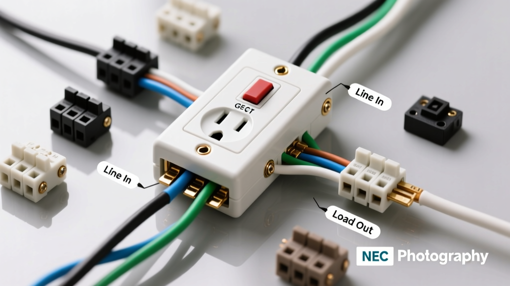
- GFCI Trip Test (If applicable): If the extended outlet is downstream of a GFCI, press the black trip button on the tester. The donor GFCI should immediately trip, cutting power to your new outlet. If it does not, your equipment grounding conductor (EGC) is not continuous, and the outlet is unsafe for use in wet locations.
- Voltage Drop Test: Plug in a known 1500-watt resistive load (like a heat gun or space heater) into the new extended outlet. Measure the voltage at the receptacle. If the voltage drops below 114V (on a 120V nominal system) while the load is running, your wire run is too long for 12 AWG, or you have a high-resistance connection at a wire nut.
Summary: Never Skip the Diagnostics
Choosing to extend an electrical outlet is a highly effective way to add functionality to a room, but it fundamentally alters the electrical dynamics of the donor circuit. By rigorously testing the amperage headroom, calculating NEC box fill volumes, eliminating backstabbed connections, and verifying terminal torque, you ensure your new receptacle is not just functional, but exceptionally safe for decades to come.