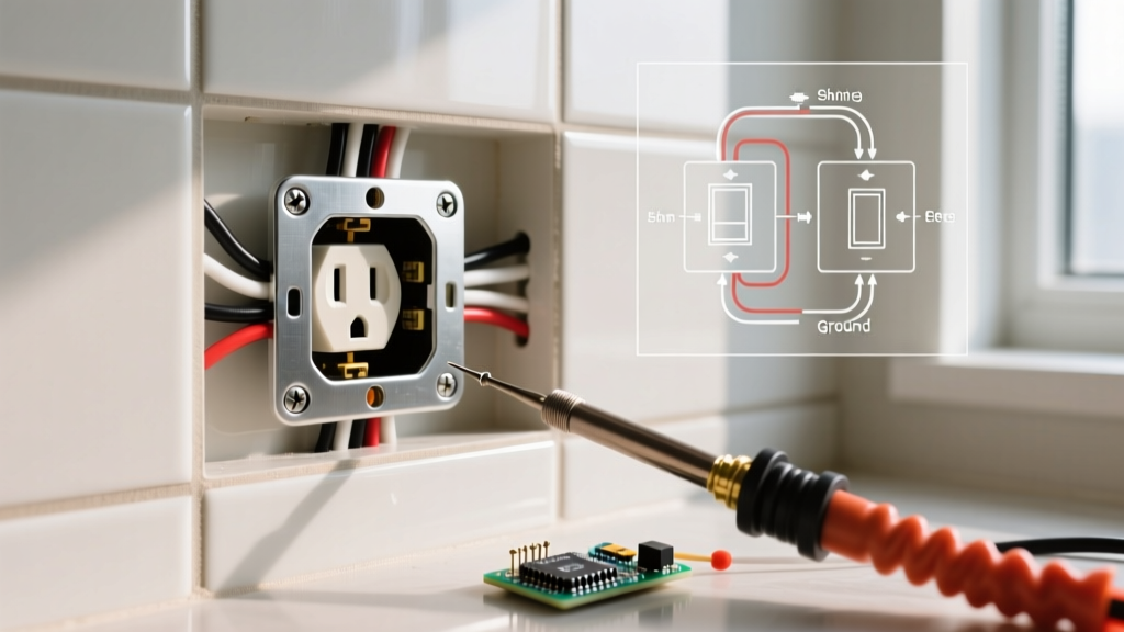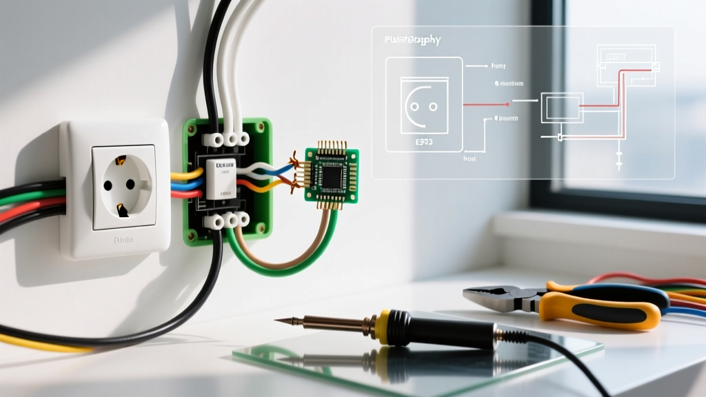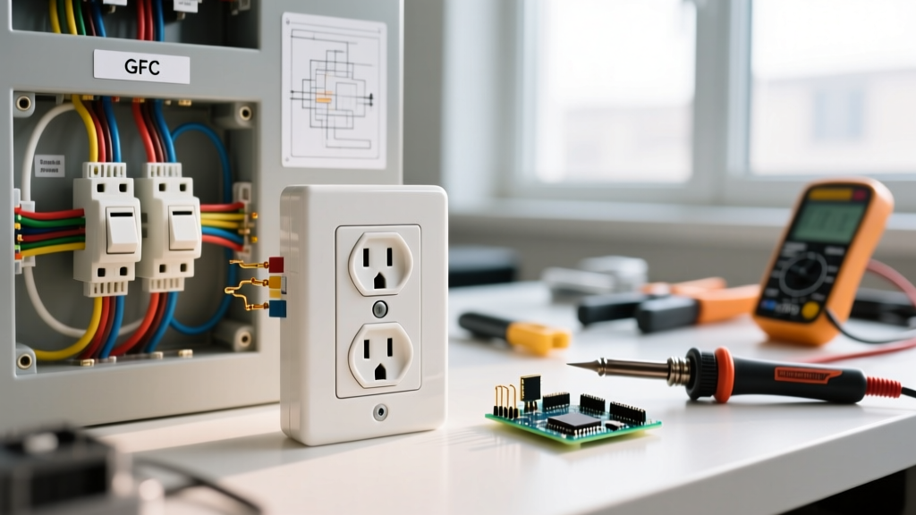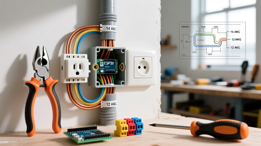

The Critical Role of the Electric Plug Wiring Diagram in Field Testing
Whether you are troubleshooting a tripped breaker, repairing a heavy-duty appliance cord, or commissioning new industrial equipment, the electric plug wiring diagram is your foundational blueprint. A plug is not merely a physical connector; it is a precisely engineered interface governed by strict National Electrical Manufacturers Association (NEMA) standards. Miswiring a plug—even by a single terminal—can result in catastrophic equipment failure, severe electrical shock, or fatal arc flash incidents.
According to the OSHA Electrical Safety Standards, faulty wiring and improper cord connections are among the leading causes of workplace electrical fatalities. This inspection and testing guide moves beyond basic DIY advice, providing electrical professionals and advanced hobbyists with the exact diagnostic procedures, torque specifications, and testing matrices required to verify plug integrity against its schematic.
Decoding NEMA Configurations: Beyond the Standard 5-15P
Before applying a multimeter, you must correctly identify the plug configuration. The standard household plug is the NEMA 5-15P (125V, 15A, 2-pole, 3-wire). However, inspection protocols change drastically when dealing with higher amperage or 240V configurations. Always cross-reference the physical plug with the manufacturer's electric plug wiring diagram before energizing the circuit.
Common NEMA Plug Configurations and Wire Mapping
| NEMA Config | Voltage / Amperage | Hot (Line) | Neutral | Ground | Min. Wire Gauge (Copper) |
|---|---|---|---|---|---|
| 5-15P | 125V / 15A | Brass (Black) | Silver (White) | Green (Bare/Green) | 14 AWG |
| 5-20P | 125V / 20A | Brass (Black) | Silver (White) | Green (Bare/Green) | 12 AWG |
| 6-50P | 250V / 50A | Brass (Black/Red) | Brass (Black/Red) | Green (Bare/Green) | 6 AWG |
| L14-30P | 125/250V / 30A | Brass (X & Y) | Silver (White) | Green (Green) | 10 AWG |
Note: The NEMA WD6 Wiring Devices Standard dictates the exact dimensional and terminal requirements for these configurations. Never force a plug into a receptacle that does not match its NEMA designation.
Essential Diagnostic Tools for Plug Inspection
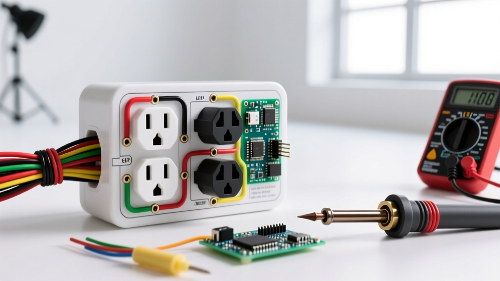
Relying on visual inspection alone is insufficient. Modern electrical diagnostics require precision instruments to verify continuity, polarity, and voltage drop under load. Equip your toolkit with the following:
- Clamp Multimeter (e.g., Fluke 376 FC): Priced around $350, this allows for non-contact current measurement and precise AC/DC voltage testing. Essential for verifying load balance on 240V split-phase plugs.
- Receptacle & Plug Tester (e.g., Klein Tools RT250): A $40 GFCI and wiring fault tester that quickly identifies open grounds, reverse polarity, and open neutrals on standard 5-15P and 5-20P plugs.
- Insulated Torque Screwdriver: Terminal screws on 15A and 20A plugs require a specific torque—typically 12 to 14 in-lbs. Under-torquing causes arcing; over-torquing strips the brass threads or crushes the stranded wire.
- Insulation Resistance Tester (Megohmmeter): For industrial 4-wire plugs, a Megger test at 500V DC ensures the cord jacket and internal insulation haven't degraded due to heat or physical abrasion.
Step-by-Step Testing Protocol Using the Wiring Diagram
Follow this systematic approach to validate a newly wired or suspect plug. Warning: Steps 3 and 4 involve live voltage. Only proceed if you are qualified and wearing appropriate PPE.
Phase 1: De-energized Continuity and Mechanical Inspection
- Strain Relief Verification: Tug the cord with approximately 30 lbs of force. The cord grip must hold the outer jacket, not the individual internal conductors.
- Terminal Torque Check: Verify that the hot, neutral, and ground screws are tightened to the manufacturer's spec (usually 14 in-lbs). Ensure no stray copper strands ("whiskers") are protruding from the terminal, which can cause short circuits.
- Continuity Mapping: Set your multimeter to the continuity setting (diode symbol). Touch one probe to the brass hot prong and the other to the black wire's terminal inside the plug. It should read near 0.00 ohms. Repeat for the silver/white and green/bare paths. Cross-check against your electric plug wiring diagram to ensure no cross-connections exist.
Phase 2: Energized Voltage and Polarity Testing
- Open Circuit Voltage: Plug the cord into a known-good, GFCI-protected receptacle. Set your multimeter to AC Voltage (V~). Measure Hot-to-Neutral (should read 118V–122V), Hot-to-Ground (118V–122V), and Neutral-to-Ground (should read < 2.0V). A high Neutral-to-Ground voltage indicates a shared neutral fault or an overloaded circuit upstream.
- Load Testing: Connect the intended appliance. Use a clamp meter around the hot conductor to verify the amperage draw matches the appliance nameplate. If a 15A plug is drawing 16A continuously, the wiring diagram dictates an immediate upgrade to a 20A circuit and plug.
Expert Insight: When testing 240V NEMA 6-50P plugs (common for EV chargers and welders), there is no neutral. You must measure Line 1 to Line 2 (expecting ~240V) and Line 1 to Ground (~120V), then Line 2 to Ground (~120V). If Line-to-Ground reads 0V, you have a catastrophic open ground fault.
Troubleshooting Matrix: Symptoms vs. Wiring Diagram Faults
When a plug fails inspection or a connected device malfunctions, use this matrix to isolate the fault based on the physical wiring schematic.
| Observed Symptom | Tester Reading / Multimeter Data | Likely Wiring Diagram Fault | Corrective Action |
|---|---|---|---|
| GFCI trips immediately upon plug insertion | RT250 shows "Hot-Ground Reverse" | Ground wire (Green) landed on Brass (Hot) terminal | Re-terminate per diagram; inspect for internal short |
| Appliance hums, runs hot, or shocks user | Hot-to-Neutral reads 120V; Neutral-to-Ground reads 120V | Open Neutral (Silver terminal loose or wire broken) | Strip wire back 1/2", re-torque silver screw to 14 in-lbs |
| Device works, but chassis is energized | Hot-to-Ground reads 0V; Hot-to-Neutral reads 120V | Open Ground or Ground bonded to Neutral inside plug | Separate Neutral and Ground; ensure Green screw bites copper |
| Plug feels hot to the touch under normal load | Thermal camera shows 140°F+ at prongs | Undersized wire gauge or loose terminal connection | Verify AWG matches diagram; replace plug if prongs are pitted |
Advanced Diagnostics: Power Quality and Harmonics
For sensitive electronics or medical equipment utilizing hospital-grade (HG) plugs, standard voltage testing is insufficient. Modern Fluke Electrical Testing Guides recommend using a Power Quality Analyzer to inspect the plug's performance under dynamic loads. You are looking for Total Harmonic Distortion (THD) and transient voltage spikes that might bypass standard surge protectors. If the electric plug wiring diagram includes an integrated EMI/RFI filter (common in high-end audio or server rack PDUs), you must test the capacitance between the Line and Ground to ensure the filter capacitors have not shorted out, which would create a lethal shock hazard on the grounding prong.
Compliance and Final Sign-Off
Every inspected and repaired plug must be tagged with the date of inspection, the tester's initials, and the verified NEMA configuration. According to the National Electrical Code (NEC), flexible cords and plugs must be inspected before each use in commercial environments. By strictly adhering to the manufacturer's electric plug wiring diagram and utilizing the diagnostic matrices provided above, you ensure not only the longevity of the connected equipment but, more importantly, the safety of the end-user. Never bypass a ground prong, never substitute a 15A plug on a 20A load, and always verify your work with a calibrated meter.