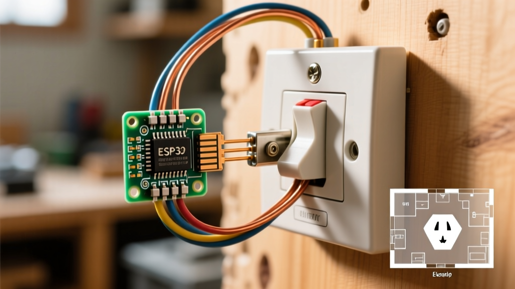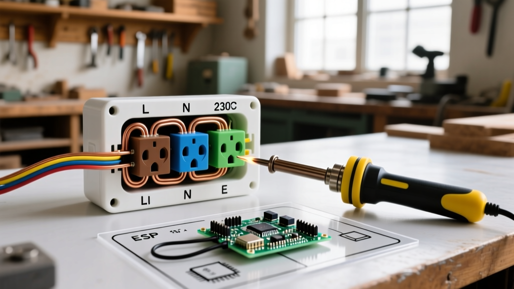

Beyond Travel Plugs: The Hardwired European Electrical Outlet Adapter
When DIYers and woodworkers import high-end European machinery—such as Festool dust extractors, Mafell track saws, or Bosch 230V routers—they quickly realize that a standard $8 plastic travel adapter is a severe fire hazard for continuous 16A loads. For permanent workshop setups, building a hardwired european electrical outlet adapter box is the only safe, code-compliant method to bridge North American 240V split-phase power with European 230V single-phase appliances. This wiring diagram reference provides the exact schematics, component lists, and edge-case troubleshooting required to build a NEMA 6-20 to Schuko Type F adapter box that meets 2026 electrical safety standards.
The Phase & Voltage Dilemma: US 240V vs. EU 230V
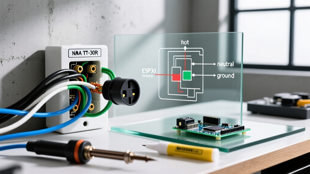
Before cutting any wire, you must understand the fundamental difference between North American and European power delivery. According to the IEC World Plugs Guide, Europe utilizes a 230V single-phase system consisting of a Line (230V), a Neutral (0V), and an Earth ground. North America utilizes a 240V split-phase system derived from a center-tapped transformer, providing two 120V 'hot' legs (L1 and L2) that are 180 degrees out of phase, plus an equipment ground.
When wiring a European electrical outlet adapter for US use, you are essentially mapping L1 to the European 'Line' and L2 to the European 'Neutral'. While the potential difference between L1 and L2 is 240V (close enough for 230V European tool tolerances), both legs carry 120V to ground. This symmetry works perfectly for resistive loads and universal motors, but it introduces complex failure modes for appliances with sensitive EMI filters, which we will address in the troubleshooting section.
Component BOM for a 20A Hardwired Adapter Box
Do not use standard residential wall plates for this adapter. You need industrial-grade, IP-rated components to handle the mechanical stress and thermal expansion of 16A continuous European loads.
- Receptacle: PCE 16A 250V IP44 Schuko Type F Panel Receptacle (with spring-loaded ground clips).
- Plug: Hubbell 20A 250V NEMA 6-20P Plug (Model: Hubbell 2620P).
- Cord: 12 AWG 3-Conductor SOOW flexible cord (Black, White, Green).
- Enclosure: Raco 4x4x2.5-inch Steel Junction Box with a blank cover plate modified for the PCE receptacle.
- Terminals: Weidmuller H12.0/14T insulated ferrules (mandatory for stranded wire in European screw terminals).
Wiring Diagram & Pinout Mapping
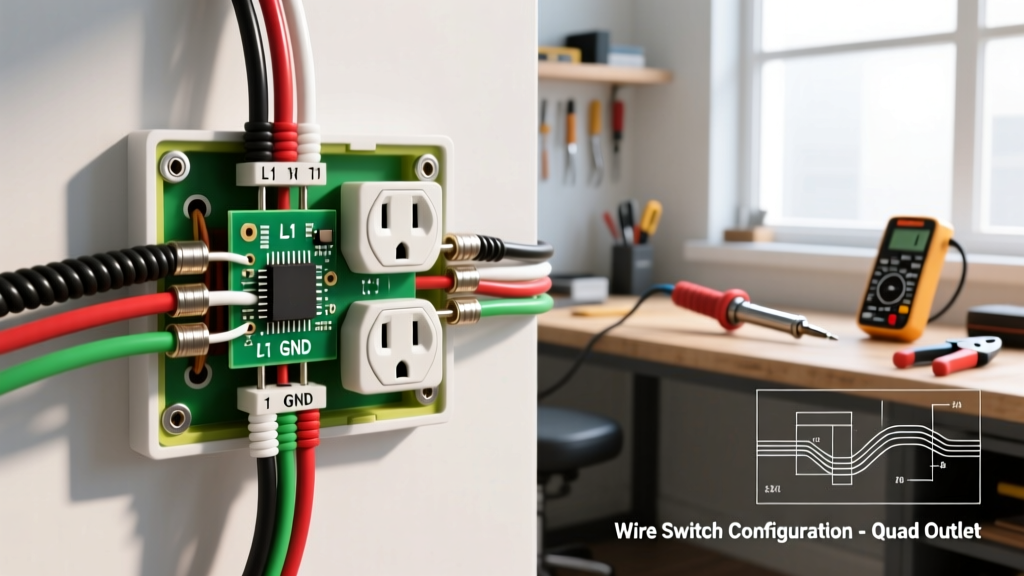
The following table dictates the exact mapping from the US SOOW cord to the Schuko Type F terminal block. Note that US electrical code requires the white wire to be re-marked with black or red tape at both ends to indicate it is being used as a hot leg, not a neutral.
| US SOOW Cord Wire | EU Schuko Type F Terminal | Function in Adapter | Voltage to Ground (US) |
|---|---|---|---|
| Black (Hot 1) | Line (L) | Phase 1 Delivery | 120V |
| White (Hot 2, Re-marked) | Neutral (N) | Phase 2 Return | 120V |
| Green (Ground) | Earth (PE) / Ground Clips | Equipment Grounding | 0V |
Step-by-Step Assembly Procedure
- Prepare the Enclosure: Use a 38mm hole saw to cut a precise opening in the steel junction box cover plate for the PCE Schuko receptacle. Deburr the edges to prevent cord chafing.
- Strip and Ferrule: Strip 12mm of insulation from the SOOW conductors. Crimp insulated ferrules onto the stranded copper using a ratcheting ferrule crimper. Never insert bare stranded wire into European screw terminals; the screws will shear the copper strands, causing high-resistance hot spots.
- Terminate the Receptacle: Connect the Black wire to 'L', the re-marked White wire to 'N', and the Green wire to the central 'PE' screw. Torque the terminal screws to exactly 1.2 Nm (10.6 in-lbs) using a calibrated torque screwdriver to prevent thermal loosening.
- Secure the Ground Clips: Ensure the green wire is also bonded to the metal junction box using a green grounding screw and a 12 AWG pigtail. The Schuko standard relies on the side grounding clips making contact with the plug, but the internal box must remain bonded to the PE circuit.
- Seal and Test: Attach the cover plate, install a cord grip strain relief on the side of the junction box, and test with a multimeter. You should read ~240V between L and N, and ~120V between L-PE and N-PE.
The EMI Filter Edge Case: Why GFCIs Trip
The most common failure mode when using a European electrical outlet adapter on a US 240V circuit is nuisance GFCI tripping. High-end European appliances (like Jura espresso machines or CNC spindle controllers) utilize internal Schaffner EMI filters. These filters contain Y-capacitors wired between Line-to-Ground and Neutral-to-Ground to suppress high-frequency noise.
Engineering Insight: In Europe, the Neutral-to-Ground Y-capacitor sees 0V, so no current leaks to ground. In a US split-phase adapter, the 'Neutral' terminal is actually L2, which carries 120V to ground. This forces the Y-capacitor to pass continuous capacitive leakage current to the ground wire.
If your US 240V circuit is protected by a double-pole GFCI breaker (as required by the NFPA 70: National Electrical Code (NEC) for garage and workshop receptacles), this 5mA to 15mA continuous leakage will instantly trip the breaker upon powering the tool. The Solution: For sensitive electronics, you must interpose a 240V-to-230V isolating transformer with a bonded neutral on the secondary side, rather than using a direct hardwired adapter pigtail.
NEC Code Compliance & 2026 Updates
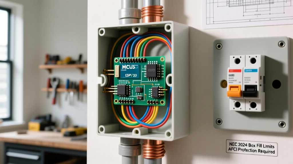
As of the 2026 NEC cycle, the requirements for ground-fault protection in workshop environments have expanded. Article 210.8(F) mandates GFCI protection for all 125V through 250V receptacles supplied by single-phase branch circuits rated 150 volts or less to ground. Because a NEMA 6-20 split-phase circuit operates at 120V to ground, your adapter box must be plugged into a GFCI-protected circuit if located in a garage, basement, or workshop. Furthermore, the adapter box itself must be clearly labeled with a warning tag: 'WARNING: 240V Split-Phase Input. Do not use with appliances requiring a bonded 0V Neutral.'
Troubleshooting Common Adapter Wiring Failures
1. Tool Runs, but Chassis Reads 120V with a Non-Contact Tester
Cause: Floating ground or missing PE bond. European Schuko plugs do not have a dedicated ground pin; they rely on the side metal clips. If your adapter receptacle's internal ground clips are bent or if the green wire was not bonded to the junction box, the chassis will float at 120V due to the EMI filter capacitive voltage divider.
Fix: Open the adapter box, verify continuity from the PE terminal to the metal box, and ensure the PCE receptacle's side clips are applying at least 4mm of deflection pressure against the plug.
2. Immediate Thermal Overload on the NEMA 6-20 Breaker
Cause: Inrush current mismatch. European 230V motors often have massive un-compensated inrush currents (up to 60A for a 3HP compressor). A standard US thermal-magnetic breaker may interpret this as a short circuit.
Fix: Upgrade the US circuit breaker to a 'D-Curve' or 'HACR' type breaker designed for high inrush motor loads, or install a soft-start module (like a NEMA 6-20 inline soft starter) between the wall and the adapter box.
3. Reversed Polarity Warnings on Imported Lab Equipment
Cause: Some European medical or laboratory equipment actively monitors the voltage between the Neutral pin and the Earth pin. Because US split-phase provides 120V on both pins, the equipment's internal logic board detects a 'fault' and refuses to power on.
Fix: Direct adapter wiring will not work. You must use a 2kVA step-up/step-down isolation transformer to create a true single-phase 230V output with a bonded neutral reference.