
Why Standard Outlets Fail in Outdoor Environments
Installing outdoor power is a common DIY project for homeowners looking to support smart landscaping, holiday lighting, or outdoor power tools. However, taking a standard indoor receptacle and placing it outside is a critical safety hazard. Standard outlets lack the UV stabilization and corrosion-resistant metallurgy required to survive rain, humidity, and temperature fluctuations. Over time, the internal brass contacts oxidize, increasing electrical resistance, generating excess heat, and creating a severe fire or shock hazard. According to the U.S. Consumer Product Safety Commission (CPSC), ground-fault and weather-related electrical failures remain a leading cause of outdoor electrocution and structural fires.
This beginner tutorial will walk you through the exact process of replacing or installing a weather resistant electrical outlet, ensuring your setup is safe, durable, and fully compliant with modern electrical codes.
Decoding the 'WR' Stamp and NEC Requirements
Before touching a single wire, you must understand what the law requires. The National Electrical Code (NEC), specifically Article 406.9, mandates strict rules for outdoor receptacles. You can review the core standards via the National Fire Protection Association (NFPA) NEC directory.
The Golden Rule of Outdoor Receptacles: Any 15-amp or 20-amp, 125-volt or 250-volt receptacle installed in a damp or wet location must be listed as Weather Resistant (WR), protected by a Ground Fault Circuit Interrupter (GFCI), and fitted with an extra-duty, in-use weatherproof cover.
What makes a weather resistant electrical outlet different from a standard GFCI? The 'WR' stamp on the face of the device indicates three specific manufacturing upgrades:
- UV-Resistant Polycarbonate: The plastic face and body will not become brittle or crack when exposed to direct sunlight over years of use.
- Corrosion-Resistant Contacts: The internal brass components are heavily nickel-plated to prevent oxidation from humidity and salt air.
- Stainless Steel Mounting Straps: The mounting yoke (the metal strap that screws into the box) is made of stainless steel to prevent rusting, which can compromise the grounding path.
Tools and Materials Breakdown
Do not cut corners on materials when working outdoors. Here is the exact bill of materials and estimated 2026 pricing for a standard single-gang replacement.
| Item | Recommended Model / Spec | Est. Cost |
|---|---|---|
| WR GFCI Receptacle | Leviton Decora 20A WR GFCI (GFNT2-W) | $28.00 - $34.00 |
| In-Use Cover | TayMac Extra Duty In-Use Cover (ML500) | $18.00 - $24.00 |
| Outdoor Sealant | GE Advanced Silicone 2 (Clear) | $6.00 - $8.00 |
| Voltage Tester | Klein Tools NCVT-3 Non-Contact Tester | $25.00 - $30.00 |
| Wire Strippers | Klein 11055 (10-20 AWG Solid/Stranded) | $22.00 - $26.00 |
Note: Always use 20-Amp rated WR GFCIs for outdoor circuits, even if the breaker is 15-Amp. Outdoor tools (like pressure washers and table saws) draw heavy startup surges, and the heavier internal contacts of a 20-Amp receptacle handle this heat much better.
Step-by-Step Installation Guide
Step 1: De-energize and Verify the Circuit
Locate your main electrical panel and turn off the breaker supplying the outdoor circuit. Never assume the power is off based on the switch position. Use your non-contact voltage tester (like the Klein NCVT-3) to test the top and bottom slots of the existing outlet. Furthermore, plug in a simple lamp or receptacle tester to confirm zero power. For maximum safety, lock out the breaker panel if others are in the home.
Step 2: Identify Line vs. Load (The #1 Beginner Trap)
Remove the old outlet and pull the wires out of the box. You will typically see two cables entering the box (one bringing power from the panel, one taking power downstream to other outlets). GFCI receptacles have two sets of terminals: LINE and LOAD.
- LINE: Connects to the wires bringing power from the breaker panel. This is mandatory for the GFCI to power itself and its internal protection circuitry.
- LOAD: Connects to the wires sending power downstream to other outlets. If you want downstream outlets to also have GFCI protection, wire them here. If this is the end of the run, or you only want this specific outlet protected, cap the downstream wires and only use the LINE terminals.
Pro Tip: Before disconnecting the old standard outlet, use a piece of red electrical tape to flag the 'hot' wire (usually black) that was connected to the brass screw. This is your LINE hot wire.
Step 3: Prep and Terminate the Conductors
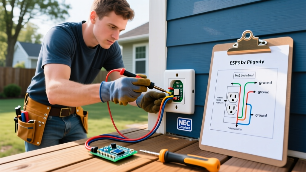
Using your wire strippers, strip exactly 3/4-inch of insulation from your 12 AWG or 14 AWG solid copper wires. Do not use the 'push-in' backstab holes on the back of the GFCI; these are notorious for failing outdoors due to thermal expansion and contraction. Instead, use the side terminal screws. Hook the bare copper ground wire around the green ground screw, the white neutral wires to the silver LINE screws, and the black hot wires to the brass LINE screws. Tighten the screws firmly. If you own a torque screwdriver, tighten to the manufacturer's specification (typically 14 in-lbs) to prevent 'cold flow' loosening over time.
Step 4: Mount and Seal the Device
Wrap the sides of the WR GFCI body with two layers of high-quality vinyl electrical tape to cover the exposed terminal screws. This prevents accidental shorting against a metal outdoor box. Carefully fold the wires in a Z-pattern and push the device into the box. Secure it with the provided stainless steel mounting screws.
The Caulk Dam Technique: Before attaching the faceplate or cover, run a continuous bead of GE Advanced Silicone 2 along the top and both sides of the mounting flange where it meets the siding or stucco. Leave the bottom edge un-caulked. This allows any condensation that builds up inside the box to drain out the bottom, while the top and sides remain sealed against driving rain.
Step 5: Attach the Extra-Duty In-Use Cover
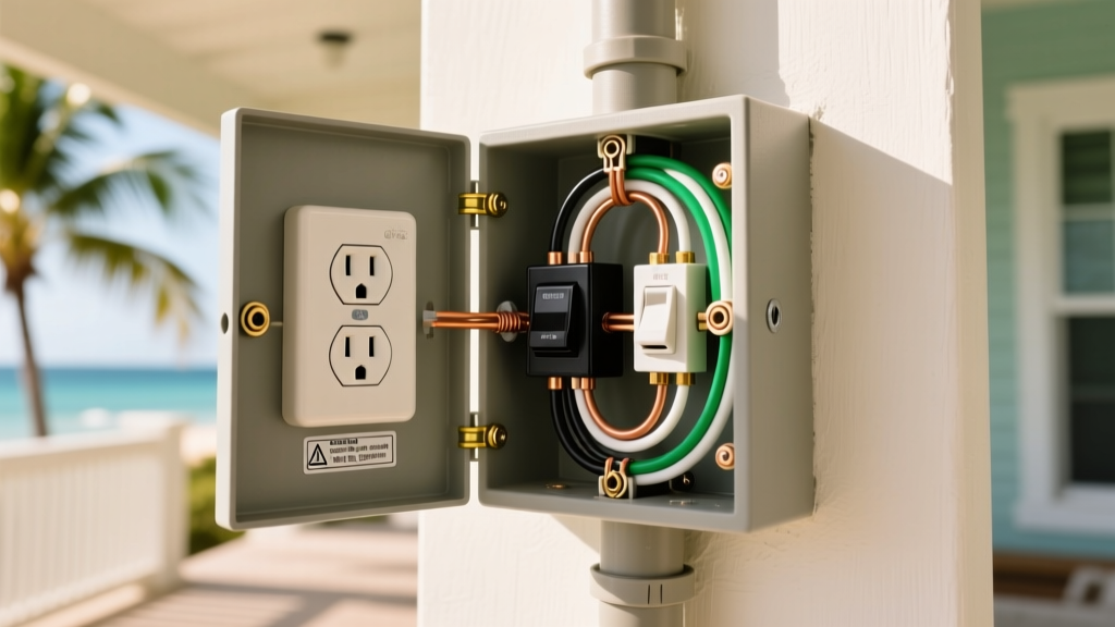
An outdoor outlet is only as weatherproof as its cover. Standard flat covers are illegal for new installations because they leave plugs exposed to rain. Install an 'Extra-Duty' in-use cover (like the TayMac ML500), which features a deep bubble dome that closes completely even when a heavy-duty extension cord is plugged in. Ensure the rubber gasket on the cover sits perfectly flush against the siding or the outlet's weatherproof flange.
Common Beginner Mistakes to Avoid
- Using Indoor Wire Nuts: Standard orange or yellow wire nuts can corrode outdoors. Use silicone-filled wire connectors (like Ideal Aqua-Seal) or heat-shrink butt connectors for any splices made inside the outdoor box.
- Over-tightening the In-Use Cover Hinge: The hinge on bubble covers is designed to pivot freely. If you overtighten the mounting screws on the cover, the plastic will warp, preventing the lid from closing fully and defeating the weatherproof seal.
- Ignoring Box Depth: WR GFCIs are physically deeper than standard receptacles due to their internal electronics. If you are installing a new box, use an 'extra-deep' PVC or cast aluminum outdoor box (minimum 22 cubic inches) to comfortably fit the device and 12 AWG wires without crushing them.
Frequently Asked Questions
Can I use a standard indoor GFCI with a weatherproof cover?
No. While the cover protects against direct rain, outdoor environments suffer from high humidity, condensation, and temperature swings. A standard indoor GFCI will eventually suffer from internal corrosion on its sensing circuitry, leading to 'nuisance tripping' or, worse, a failure to trip during a real ground fault. The NEC strictly requires the 'WR' designation for all outdoor 15A/20A receptacles.
Why does my new outdoor GFCI keep tripping when it rains?
If your weather resistant electrical outlet trips during storms, the issue is rarely the outlet itself. It is almost always a failure in the sealing method. Check the top edge of your in-use cover for gaps in the silicone caulk. Additionally, inspect the cord you have plugged in; if the cord's jacket is cracked or the plug end is not seated tightly, water can wick up the copper strands via capillary action directly into the GFCI terminals.
Do I need a GFCI breaker in the panel if I use a WR GFCI outlet?
No, and in fact, it is discouraged to use both. Having a GFCI breaker at the panel and a GFCI receptacle at the outlet creates 'redundant protection.' While not strictly illegal in all jurisdictions, it leads to severe nuisance tripping and makes troubleshooting a nightmare, as you will have to walk to the main panel to reset the circuit every time the outdoor outlet trips. Use a standard thermal-magnetic breaker in the panel and rely on the WR GFCI receptacle for localized ground-fault protection.
Final Safety Verification
Once your installation is complete and the breaker is turned back on, press the 'TEST' button on the WR GFCI. You should hear a distinct click, and the 'RESET' button should pop out. Plug in a receptacle tester with a GFCI testing function to verify the wiring is correct. Press the 'RESET' button to restore power. By following these exact specifications, your outdoor power setup will remain safe, code-compliant, and fully operational for years to come. For further reading on outdoor electrical safety practices, consult the Occupational Safety and Health Administration (OSHA) electrical safety guidelines.