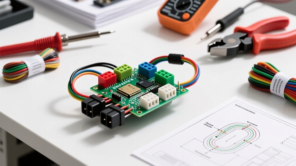

Decoding the Standard Electrical Socket Wiring Diagram
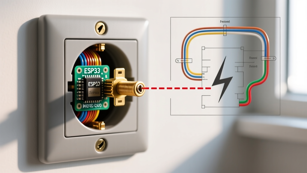
Understanding an electrical socket wiring diagram is the foundational skill for any residential electrical project. Whether you are replacing a damaged duplex receptacle or wiring a new branch circuit, the diagram serves as your blueprint for mapping alternating current (AC) from the breaker panel to the point of use. At its core, a standard 120-volt North American receptacle diagram illustrates three critical pathways: the ungrounded conductor (hot), the grounded conductor (neutral), and the equipment grounding conductor.
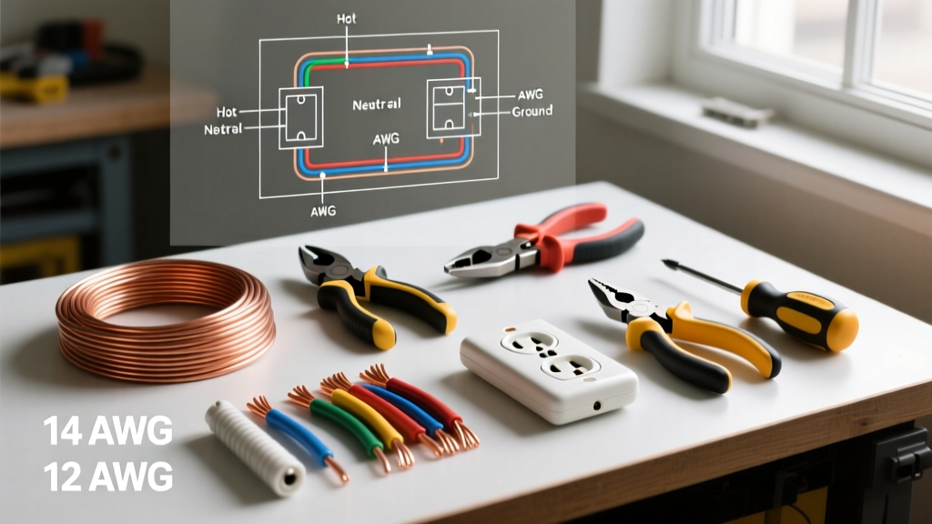
In modern residential wiring governed by the NEC (National Electrical Code), the color-coding is strictly enforced. Black or red insulation designates the hot wire, which connects to the brass-colored terminal screws. White or gray insulation designates the neutral wire, terminating at the silver-colored screws. Finally, the bare copper or green-insulated ground wire maps to the green grounding screw. Misinterpreting these pathways on your electrical socket wiring diagram can result in reversed polarity, creating a severe shock hazard where the outer shell of an appliance becomes energized.
CRITICAL SAFETY WARNING: Before interacting with any wiring diagram or physical receptacle, verify that the circuit breaker is locked out and tagged out (LOTO). According to OSHA electrical safety standards, never rely solely on a wall switch to de-energize a circuit. Always use a CAT III or CAT IV rated non-contact voltage tester to confirm zero energy state at the receptacle.
Essential Tools and Materials for Code Compliance
Executing the physical installation based on your electrical socket wiring diagram requires precision tools. The days of simply tightening screws by feel are over; modern electrical codes mandate specific torque values to prevent thermal expansion failures. Below is the required toolkit for a professional-grade 15-amp or 20-amp receptacle installation in 2026.
| Tool / Material | Specification / Model | Estimated Cost |
|---|---|---|
| Wire Strippers | Klein Tools 11055 (10-20 AWG) | $28.50 |
| Torque Screwdriver | Klein Tools 32500 (Set to 14 in-lbs) | $65.00 |
| Receptacle (Standard) | Leviton T5262-W (15A Tamper-Resistant) | $3.25 / ea |
| Wire Connectors | WAGO 221 Series Lever Nuts (413) | $0.60 / ea |
| Voltage Tester | Milwaukee 2202-20 (Dual Range) | $34.99 |
Step-by-Step Installation: Translating Diagram to Reality
Step 1: Cable Preparation and Stripping
When routing 14/2 NM-B (Romex) for 15-amp circuits or 12/2 NM-B for 20-amp circuits, the physical preparation of the cable dictates the success of the termination. Using a cable ripper, strip the outer PVC jacket back exactly 3/4 of an inch from the edge of the electrical box. This ensures the jacket enters the box but does not crowd the internal wiring space. Next, use your Klein 11055 strippers to remove exactly 5/8 of an inch of insulation from the individual conductors. Stripping too little will result in insulation getting caught under the terminal screw (a major fire hazard), while stripping too much will leave exposed bare wire outside the terminal, creating a shock risk.
Step 2: Forming the Shepherd's Hook
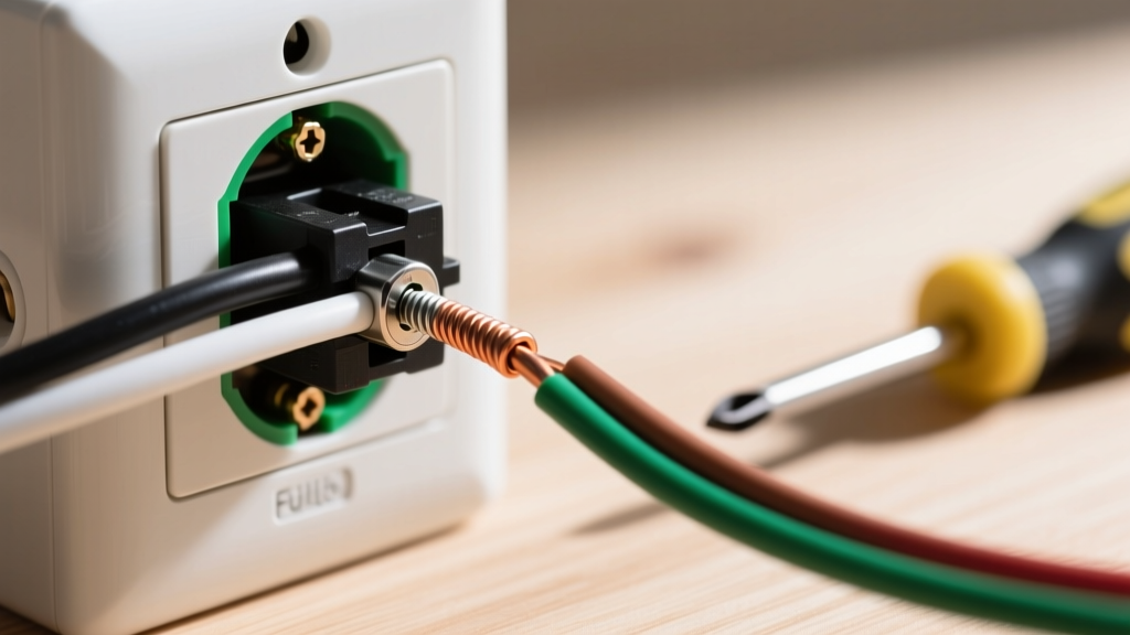
Your electrical socket wiring diagram will show the wires terminating at the side screws. Using needle-nose pliers, bend the stripped end of the wire into a tight 'shepherd's hook' or 'J-hook'. The hook must be oriented clockwise. When you tighten the terminal screw clockwise, the loop will naturally pull tighter around the screw shaft. If hooked counter-clockwise, the tightening action will push the wire out from under the screw head, leading to a high-resistance connection and eventual arcing.
Step 3: Side-Wiring vs. Back-Stabbing (Failure Modes)
Many modern diagrams show a 'push-in' or 'back-wire' option on the rear of the receptacle. Avoid standard push-in back-stabs at all costs. These rely on a small internal brass spring clip to grip the wire. Over years of thermal cycling (heating under load and cooling), these clips lose tension, leading to loose connections, voltage drops, and electrical fires. Always use side-wiring (the brass/silver screws) or, if the receptacle features 'screw-clamp' back-wiring (where tightening the screw pulls a pressure plate tight against the wire), use that method. Side-wiring remains the gold standard for residential durability.
Step 4: Torque Verification
The National Fire Protection Association (NFPA) updated the NEC to require that terminals be tightened to the manufacturer's specified torque. For standard Leviton 15A and 20A duplex receptacles, this value is typically 14 inch-pounds. Use a calibrated torque screwdriver to tighten the brass, silver, and green screws. Under-torquing causes arcing; over-torquing can strip the brass threads or snap the screw head.
GFCI Diagram Variations: LINE vs. LOAD Mapping
When your project involves wet locations (kitchens, bathrooms, garages, exteriors), your electrical socket wiring diagram must incorporate a Ground Fault Circuit Interrupter (GFCI). The Consumer Product Safety Commission (CPSC) heavily emphasizes GFCI installation to prevent fatal electrocution. The most common point of failure in GFCI installation is misinterpreting the LINE and LOAD terminals on the back of the device.
- LINE Terminals: These connect to the incoming power feed directly from the breaker panel. The diagram will always show the source hot and neutral landing here first.
- LOAD Terminals: These connect to downstream receptacles, extending GFCI protection to other outlets on the same circuit.
Edge Case Failure: If you wire the incoming power to the LOAD terminals and cap off the LINE terminals, the GFCI will not function. It may appear to work if downstream loads are attached, but the internal sensing coil will be bypassed, rendering the shock protection entirely useless. Always use the included yellow tape to cover the LOAD terminals until you are certain downstream protection is required.
Multi-Receptacle Pigtailing Strategy
When wiring multiple standard duplex receptacles in a daisy-chain configuration, never use the receptacle itself as the splice point for the neutral or hot continuation. If the receptacle is removed for replacement, the downstream outlets will lose their neutral path, potentially causing severe overvoltage on a multi-wire branch circuit. Instead, utilize a pigtailing method. Use WAGO 221 lever nuts to splice the incoming wire, the outgoing wire, and a 6-inch pigtail of the same gauge wire. Connect the pigtail to the receptacle terminal. This ensures circuit continuity regardless of the receptacle's physical presence.
Troubleshooting Common Diagram Misinterpretations
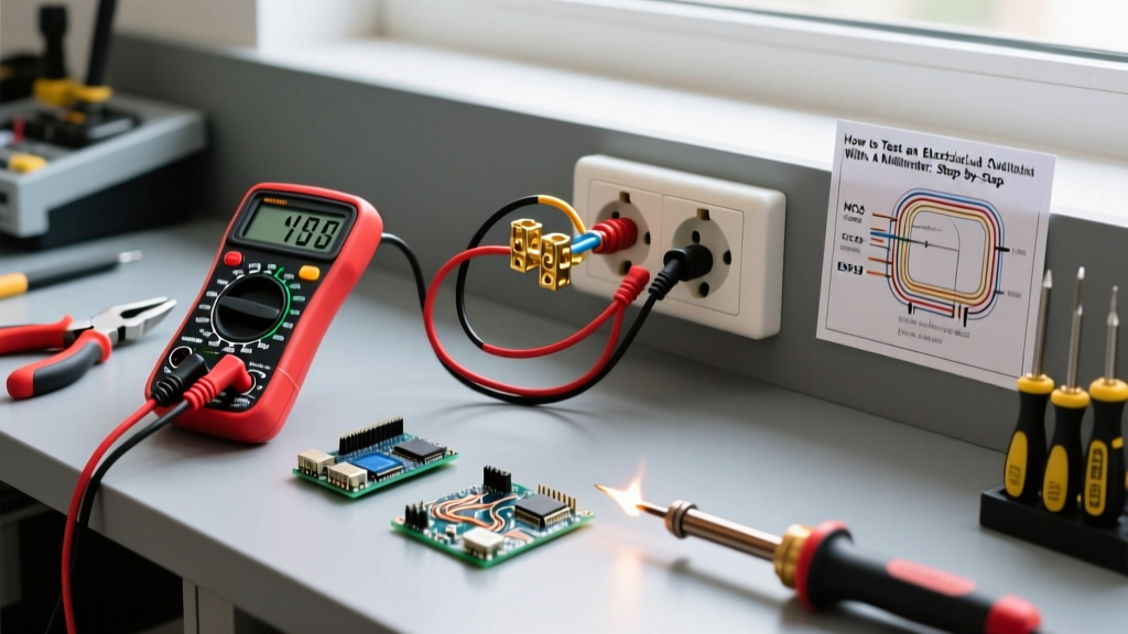
After completing the physical installation based on your electrical socket wiring diagram, test the circuit before installing the wall plate. Use a professional receptacle tester (like the Klein Tools RT250) to verify the wiring logic.
| Tester Reading | Diagram Translation Error | Corrective Action |
|---|---|---|
| Open Ground | Ground wire not terminated to green screw or broken upstream. | Verify bare copper connection at receptacle and panel ground bar. |
| Reverse Polarity | Hot (black) wired to silver screw; Neutral (white) wired to brass. | Swap the black and white wires to their correct color-coded terminals. |
| Hot/Neutral Reverse | Upstream panel wiring error or misidentified wire colors in old NM cable. | Trace circuit to panel; re-identify white wire with black tape if used as hot in a switch loop. |
Final Inspection and Wall Plate Installation
Once the tester confirms 'Correct' wiring, carefully fold the wires into the back of the electrical box. Push the receptacle flush against the drywall or plaster. Use the built-in leveling tabs on the yoke (the metal strap) to ensure the outlet sits perfectly straight. Drive the 6-32 mounting screws into the box ears, tightening them evenly to avoid cracking the plastic faceplate. Finally, install a screwless or standard nylon wall plate. Your adherence to the electrical socket wiring diagram, combined with precise torque and termination techniques, guarantees a safe, code-compliant installation that will operate reliably for decades.