
Anatomy of a Standard 120V Receptacle Wiring Diagram
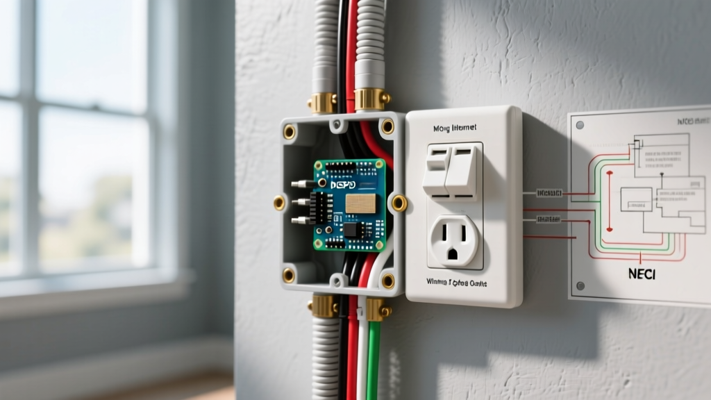
When adding an electrical outlet to an existing branch circuit or running a new line, understanding the fundamental wiring diagram is non-negotiable. A standard 15-amp or 20-amp 120V receptacle operates on a three-wire system: an ungrounded conductor (hot), a grounded conductor (neutral), and an equipment grounding conductor (ground). Misinterpreting these paths is the leading cause of reversed polarity, tripped breakers, and severe shock hazards.
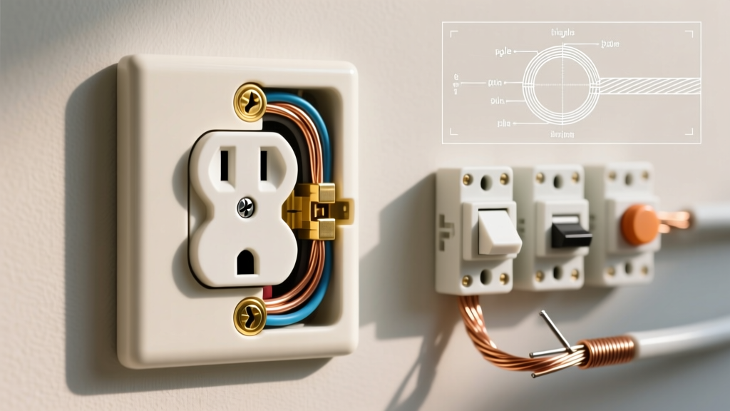
For this reference, we are focusing on a standard NEMA 5-15R or 5-20R duplex receptacle, such as the Leviton T5262 (15A Tamper-Resistant) or the Hubbell 5262. These spec-grade devices feature internal screw-terminal pressure plates that allow for secure side-wiring, which is heavily preferred over back-stab (push-in) connections that are prone to thermal failure under continuous loads.
The Core Terminal Map
- Brass Screws (Hot/Line): Connects the black (or red) ungrounded wire. This carries the 120V potential from the panel.
- Silver Screws (Neutral): Connects the white grounded wire. This completes the circuit back to the neutral bus bar.
- Green Screw (Ground): Connects the bare copper or green insulated wire. This provides a low-impedance fault path to trip the breaker during a short circuit.
Line vs. Load: The Daisy-Chain Diagram
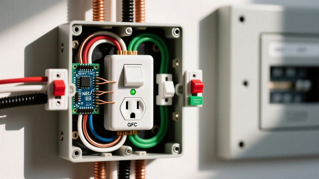
When adding an electrical outlet to the middle or end of an existing run, you must understand the difference between "Line" and "Load" terminals, especially if you are installing a GFCI receptacle. For a standard duplex receptacle, both sets of brass and silver screws are internally bridged by break-off metal fins (yokes).
Expert Insight: Never rely on the receptacle's internal yoke to splice the neutral wire for downstream outlets. The 2026 National Electrical Code (NEC) Section 300.13(B) strictly requires that the continuity of the grounded (neutral) conductor must not depend on device connections. Always use a wire nut pigtail for the neutral.
Wiring a Downstream Outlet (Standard Receptacle)
- Incoming Power (Line): The black and white wires from the panel enter the box. Strip exactly 3/4 inch of insulation using the built-in gauge on the back of the receptacle.
- Outgoing Power (To next outlet): A second set of black and white wires leaves the box to feed the next device in the daisy chain.
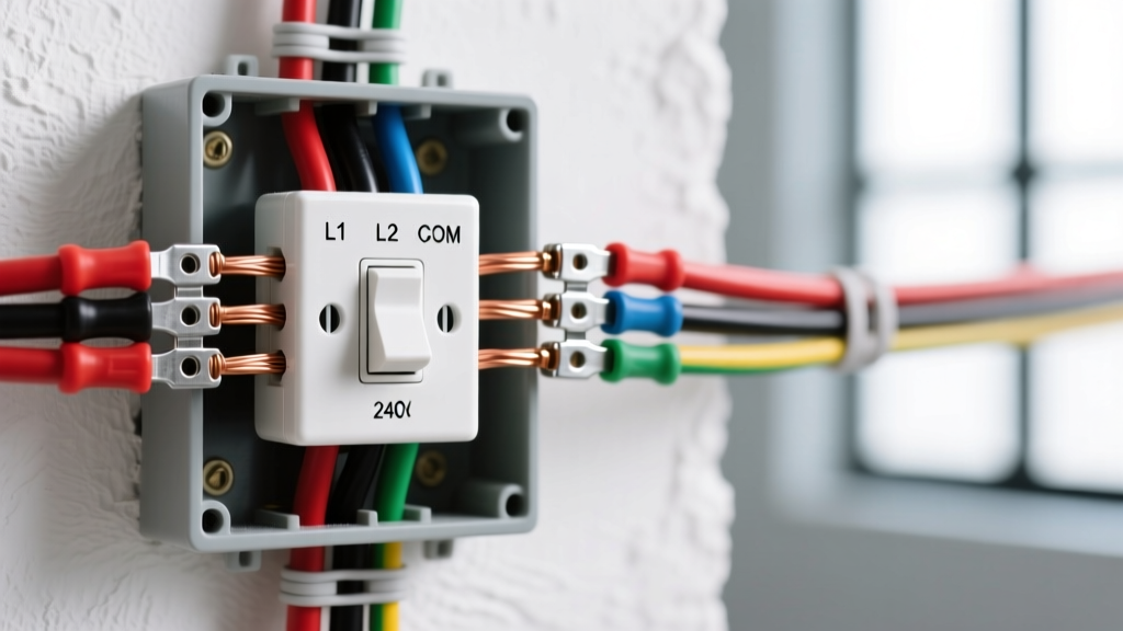
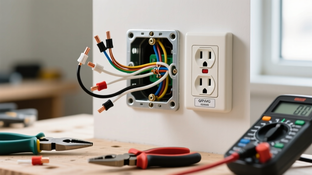
- The Pigtail Method: Instead of landing two black wires on one brass screw, twist the incoming black, outgoing black, and a 6-inch black pigtail together using an Ideal Yellow #74B wire nut. Connect the free end of the pigtail to the brass screw. Repeat for the white neutral wires.
NEC 2026 Box Fill Calculations: Don't Overstuff the Box
Before you start stripping wires, you must verify that the electrical box has adequate volume. Overcrowded boxes trap heat and make it physically impossible to fold the wires without stressing the terminal connections. According to the National Fire Protection Association (NFPA) and NEC Article 314.16, box fill is calculated by assigning a cubic inch (cu. in.) value to every wire, clamp, and device in the enclosure.
Box Fill Volume Allowance Table
| Conductor Size (AWG) | Volume Allowance per Wire (Cubic Inches) | Typical Use Case |
|---|---|---|
| 14 AWG | 2.0 cu. in. | 15-Amp lighting and receptacle circuits |
| 12 AWG | 2.25 cu. in. | 20-Amp kitchen, bathroom, and garage circuits |
| 10 AWG | 2.5 cu. in. | 30-Amp dryer or HVAC circuits (rare for standard outlets) |
Calculation Example: Adding a 15A Outlet to an Existing Run
Imagine you are adding a 14 AWG outlet to a daisy chain. The box contains:
- 4 Current-Carrying Conductors: 2 incoming/outgoing blacks, 2 incoming/outgoing whites (4 x 2.0 = 8.0 cu. in.)
- 1 Equipment Ground: All grounds count as a single volume allowance based on the largest ground in the box (1 x 2.0 = 2.0 cu. in.)
- 1 Device (Receptacle): Counts as two volume allowances based on the largest wire connected to it (2 x 2.0 = 4.0 cu. in.)
- Internal Clamps: Counts as one volume allowance (1 x 2.0 = 2.0 cu. in.)
Total Required Box Volume: 16.0 cubic inches. A standard single-gang "old work" drywall box typically offers 18 to 22 cubic inches, making it perfectly compliant. If you were using 12 AWG wire, the requirement jumps to 18.0 cubic inches, necessitating a deeper 22-cu. in. box.
Precision Execution: Stripping, Torque, and Safety
The physical execution of the wiring diagram requires precision. The U.S. Consumer Product Safety Commission (CPSC) frequently cites loose electrical connections as a primary ignition source for residential fires. To prevent this, modern electrical work demands exact torque application.
The 14 in-lbs Torque Mandate
NEC Section 110.14(D) requires that terminals be tightened to the manufacturer's specified torque. For almost all standard 15A and 20A spec-grade receptacles (like the Leviton ProGrade line), the required torque is 14 inch-pounds.
- Under-tightening: Causes micro-arcing, heat buildup, and eventual melting of the receptacle face.
- Over-tightening: Strips the brass screw threads or shears the wire, reducing the contact surface area.
Pro Tip: Invest in a dedicated inch-pound torque screwdriver, such as the Klein Tools 630, rather than guessing with a standard screwdriver.
GFCI and AFCI Mandates for New Outlets
When adding an electrical outlet in 2026, you cannot simply install a standard $1.50 duplex receptacle anywhere in the home. The NEC has aggressively expanded Ground-Fault Circuit Interrupter (GFCI) and Arc-Fault Circuit Interrupter (AFCI) requirements.
Where GFCI is Mandatory
GFCI protection monitors the current balance between the hot and neutral wires. If an imbalance of 4 to 6 milliamps is detected (indicating current is leaking to ground, possibly through a human), it trips in milliseconds.
- Kitchens (all countertop receptacles)
- Bathrooms
- Garages and unfinished basements
- Outdoor areas and crawl spaces
- Within 6 feet of a wet bar sink or laundry sink
Where AFCI is Mandatory
AFCI breakers or receptacles detect dangerous arcing conditions (sparks) that standard breakers miss, preventing hidden wall fires. AFCI protection is required for almost all 120V, single-phase, 15A and 20A branch circuits supplying outlets in living rooms, bedrooms, hallways, closets, and home offices.
Diagnostic Troubleshooting: Validating Your Wiring
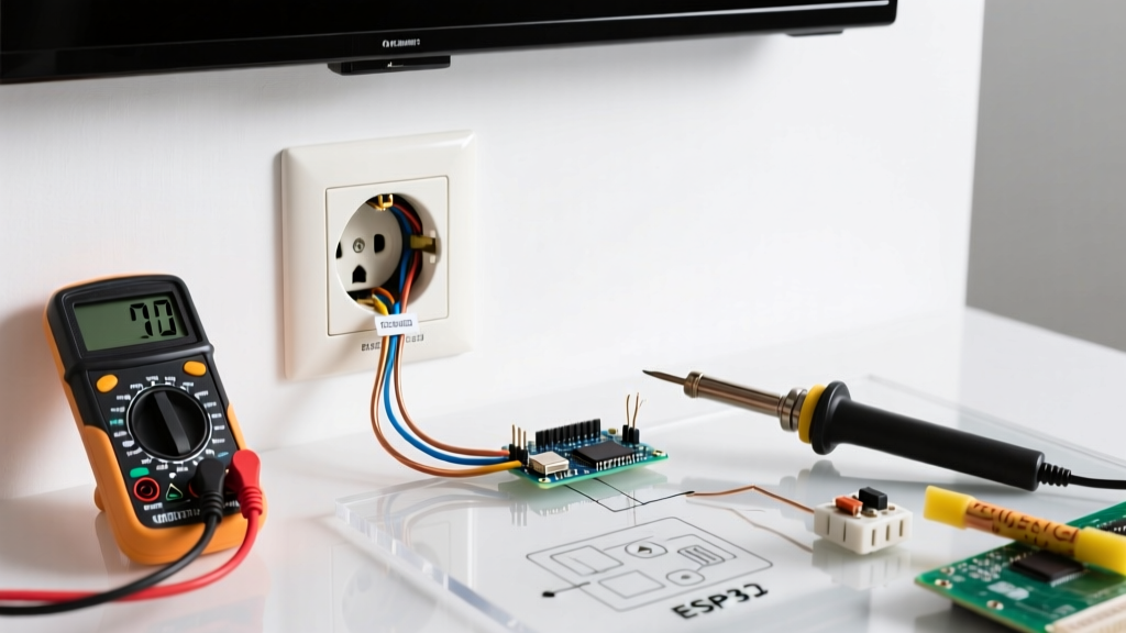
Once the outlet is wired, mounted, and the breaker is restored, do not rely on a cheap $10 plug-in tester with three neon lights. These devices cannot detect high-resistance connections or shared neutrals. Instead, use a true-RMS digital multimeter, such as the Fluke 117.
The 3-Point Voltage Test
- Hot to Neutral (H-N): Insert probes into the shorter slot (hot) and the wider slot (neutral). You should read between 115V and 125V. A reading below 110V indicates a voltage drop, likely from an undersized wire or a loose neutral connection upstream.
- Hot to Ground (H-G): Insert probes into the hot slot and the U-shaped ground hole. This should read identical to your H-N voltage (115V-125V). If it reads zero, you have an open ground (a severed or disconnected ground wire).
- Neutral to Ground (N-G): Insert probes into the neutral slot and the ground hole. This should read 0V to 2V. If you read 120V here, your hot and neutral wires are reversed (a critical shock hazard). If you read 3V to 5V, you have a heavily loaded circuit with significant neutral wire voltage drop.
Warning: The Bootleg Ground
Never connect a jumper wire between the neutral silver screw and the green ground screw to "fake" a ground on an older two-wire system. This is known as a bootleg ground. If the neutral wire ever disconnects upstream, the metal faceplate and any plugged-in appliance chassis will become energized at 120V, creating a lethal shock hazard. If no ground wire exists in the box, the NEC permits installing a GFCI receptacle and labeling it "No Equipment Ground," which provides shock protection without a physical ground wire.
Final Thoughts on Code Compliance
Adding an electrical outlet is a highly rewarding DIY project, provided you respect the physics of the circuit and the mandates of the electrical code. By adhering to strict box fill calculations, utilizing pigtails for neutral continuity, applying exact torque to terminal screws, and verifying your work with a true-RMS multimeter, you ensure your installation is as safe and reliable as one performed by a master electrician. Always consult your local Authority Having Jurisdiction (AHJ), as local municipal codes may have amendments that exceed the baseline national standards.