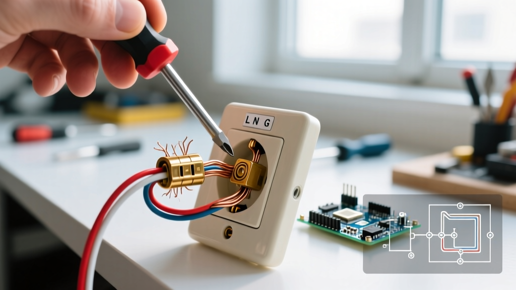

The Hidden Dangers of Failing Receptacles
When homeowners search for electrical outlet repairs, they are usually reacting to a visible symptom: a plug that falls out, a warm faceplate, or a localized power loss. However, standard 15-amp and 20-amp duplex receptacles are not designed to be internally repaired. The internal brass wipers and leaf springs fatigue over time, and attempting to bend them back into shape is a severe fire hazard. True electrical outlet repairs almost always involve a complete replacement of the device and, more importantly, correcting the termination method on the branch circuit wiring.
According to the National Fire Protection Association (NFPA), electrical distribution and lighting equipment are consistently among the leading causes of home structure fires. A significant percentage of these originate at the receptacle yoke due to high-resistance connections. This guide provides a master-level, step-by-step protocol for replacing a faulty outlet, upgrading push-in (backstabbed) connections to screw terminals, and ensuring your installation meets the latest National Electrical Code (NEC) standards.
Diagnostic Matrix: Identifying the Root Cause
Before cutting the power, map the symptom to the likely failure mode. This matrix will dictate the specific repair strategy you need to employ once the device is extracted from the junction box.
| Observed Symptom | Probable Root Cause | Required Repair Action |
|---|---|---|
| Plugs slide out easily | Fatigued internal brass wipers | Replace with new Tamper-Resistant (TR) receptacle |
| Faceplate is warm or discolored | Backstabbed wire connection arcing/high resistance | Move wire to screw terminal; trim oxidized copper |
| Half of the outlet is dead | Broken internal brass fin (tab) or loose wire nut | Verify switch loop; break tab on new outlet if needed |
| Sparks when plugging in a load | Loose neutral or line-side termination | Pigtail wires; torque screw terminals to spec |
Essential Tools and Materials (2026 Pricing)
Professional-grade electrical outlet repairs require precision tools. Cheap wire strippers can nick the copper conductor, creating a micro-fracture that snaps under thermal expansion.
- Receptacle: Leviton T5262-W (20A, 125V, Tamper-Resistant, Decora). Retail: ~$4.50. Always use 20A rated receptacles on 20A circuits, and TR models are mandated by the NEC for all dwelling unit living spaces.
- Voltage Tester: Fluke 1AC-II VoltAlert Non-Contact Voltage Tester. Retail: ~$35.00. Never rely solely on the breaker panel labeling.
- Wire Strippers: Klein Tools 11063W (8-20 AWG). Retail: ~$28.00. Features a precise shearing hole to avoid conductor gouging.
- Torque Screwdriver: CDI 401SM (10-50 in-lbs). Retail: ~$110.00. Required for NEC 110.14(D) compliance.
Step-by-Step Electrical Outlet Repairs
Step 1: Isolate and Verify the Circuit
Navigate to your main service panel and switch off the breaker controlling the target outlet. If the panel is unlabeled, plug a lamp into the outlet and turn off breakers until the lamp dies. Once the breaker is off, use your Fluke non-contact voltage tester to scan the faceplate. Remove the center screw, pull the faceplate off, and scan the receptacle slots and the edges of the yoke. The Electrical Safety Foundation International (ESFI) emphasizes that verifying the absence of voltage is the single most critical step before any physical contact with the device.
Step 2: Extract and Audit the Existing Wiring
Remove the top and bottom mounting screws holding the receptacle to the junction box. Gently pull the device outward. Do not yank the wires. Inspect the termination method:
- Backstabbed (Push-In) Connections: If wires are inserted into the small holes on the back of the yoke, they are held by a tiny brass leaf spring. These springs lose tension over years of thermal cycling (heating and cooling under load), leading to micro-arcing and melted plastic. This is the primary cause of outlet fires.
- Side-Wired (Screw Terminal): If the wires are looped around the brass screws, inspect the copper. If it is black or heavily pitted, it has oxidized due to a loose connection and must be trimmed.
- Multi-Wire Branch Circuits (MWBC): If you see a red wire and a black wire on the same yoke, you have an MWBC. Warning: Do not disconnect the white neutral wire without pigtailing it first. Breaking a shared neutral on an active MWBC can send 240V through your 120V appliances, instantly destroying them.
Step 3: Prep and Terminate (The Screw Terminal Method)
If your old outlet was backstabbed, you must release the wires by inserting a small flathead screwdriver or awl into the release slot next to the wire hole. Once removed, the wire must be transitioned to the side screw terminals.
- Trim and Strip: Cut off the last 1/2 inch of the wire that was previously inside the backstab hole, as it is likely work-hardened and scored. Strip exactly 3/4 inch of insulation using the strip gauge printed on the back of the new Leviton receptacle.
- Form the Hook: Using the needle-nose pliers on your wire strippers, bend the bare copper into a tight 'U' shape or shepherd's hook.
- Connect to Screws: Hook the bare wire around the brass (hot) and silver (neutral) screws in a clockwise direction. This ensures that as the screw tightens, it pulls the loop closed rather than pushing it out from under the screw head.
- Grounding: Attach the bare copper ground wire to the green grounding screw. If the metal junction box is also grounded, you must run a pigtail from the box to the receptacle ground screw to ensure continuous grounding.
Step 4: Torque and Mount
Modern electrical codes strictly require terminations to be torqued to the manufacturer's specifications. For the Leviton T5262-W, the required torque is 12 to 14 inch-pounds. Use a calibrated torque screwdriver to tighten the terminal screws until the tool clicks. Over-tightening can strip the brass screw head or shear the wire; under-tightening creates the exact high-resistance fault you are trying to fix. Once torqued, wrap the sides of the receptacle with electrical tape (a common electrician practice to prevent shorting against a metal box edge, though NEC allows it without tape if the box is properly sized and grounded). Fold the wires neatly in a Z-pattern into the back of the box and secure the yoke with the provided mounting screws.
Critical Edge Cases and Failure Modes
Expert Warning: The Broken Tab Scenario
If the outlet you are replacing controls a lamp via a wall switch (a split-wired receptacle), the brass fin (break-off tab) between the top and bottom hot screws on the old outlet will be snapped off. If you install a new outlet and forget to snap off this tab on the brass side, the switched half of the outlet will become constantly hot, rendering the wall switch useless. Always match the tab configuration of the old device exactly.
Code Compliance and Safety Standards
When performing electrical outlet repairs in 2026, you must adhere to the latest adopted version of the NEC (NFPA 70). Two major code requirements dictate modern receptacle replacement:
- Tamper-Resistant (TR) Mandate: All 15A and 20A receptacles in dwelling units must be TR type. These feature internal plastic shutters that only open when equal pressure is applied to both slots simultaneously, preventing children from inserting foreign objects.
- AFCI and GFCI Upgrades: If you are replacing an outlet in a kitchen, bathroom, garage, or outdoor location, NEC Article 210.8 requires Ground-Fault Circuit Interrupter (GFCI) protection. Furthermore, most living spaces now require Arc-Fault Circuit Interrupter (AFCI) protection. If your breaker panel does not have AFCI/GFCI breakers, you must install an AFCI/GFCI receptacle at the first outlet in the circuit to protect downstream devices.
By abandoning backstabbed connections in favor of properly torqued screw terminals, and by upgrading to modern TR and GFCI/AFCI devices, your DIY electrical outlet repairs will not only restore power but significantly elevate the safety profile of your home's electrical infrastructure. For further reading on residential electrical safety standards, consult the National Electrical Code documentation provided by the NFPA.