
Essential Diagnostic Tools Before You Begin
When you need to fix electrical outlet failures, guessing is dangerous and potentially lethal. A dead receptacle or an outlet that intermittently loses power is rarely a random event; it is usually the result of thermal degradation, improper termination, or an upstream fault. According to the National Fire Protection Association (NFPA), electrical distribution and lighting equipment are consistently among the top causes of home structure fires. To diagnose and repair these issues safely in 2026, you must move beyond basic screwdrivers and utilize professional-grade diagnostic equipment.
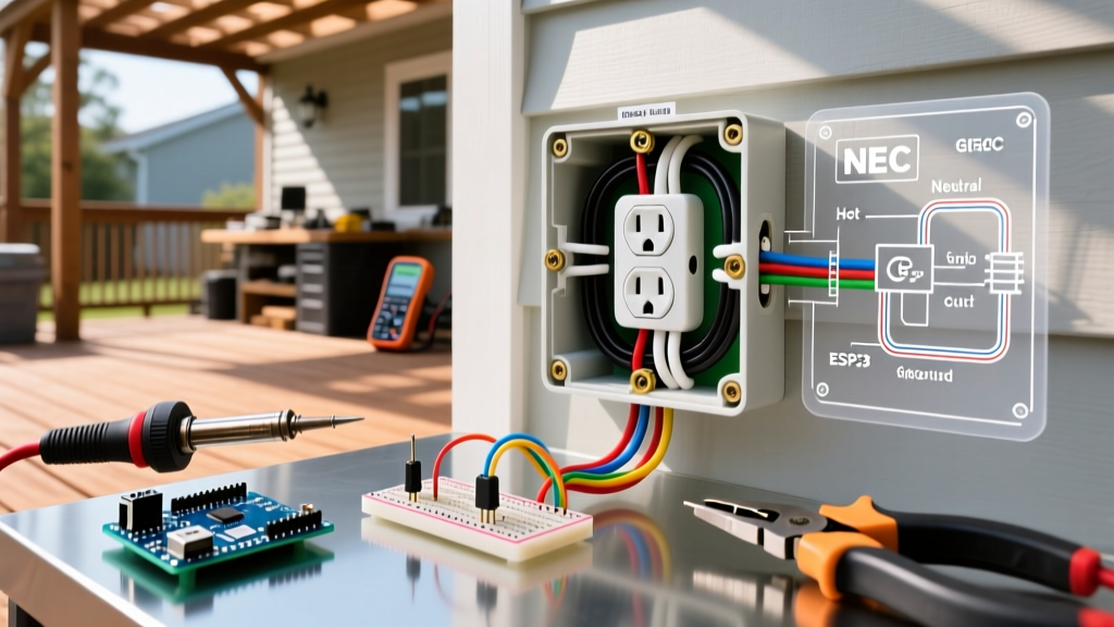
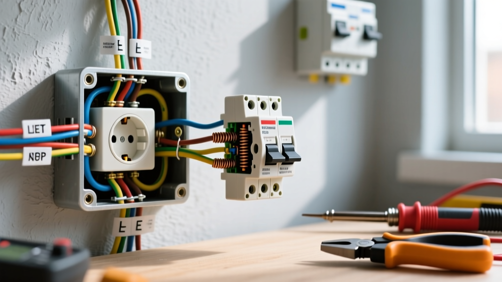
Before opening the junction box, assemble the following tools:
- Non-Contact Voltage Tester (NCVT): A dual-range tester like the Klein Tools NCVT-3 is essential for verifying the presence of standard 120V AC and low-voltage signals without exposing bare wire.
- True-RMS Multimeter: The Fluke 117 is the industry standard for verifying exact voltage drops, testing continuity, and identifying open neutrals or reversed polarity.
- Insulated Torque Screwdriver: Modern electrical codes and manufacturer specs require precise torque. A Wiha 60084 insulated torque driver set to 14 in-lbs ensures terminal screws do not loosen under thermal cycling.
- Wire Strippers and Lever Connectors: Knipex automatic strippers and Wago 221-2 lever nuts for secure, maintenance-free pigtailing.
Step 1: Isolate the Circuit and Verify Zero Energy
The first step to fix electrical outlet wiring is to kill the power at the main service panel. Do not rely solely on wall switches or GFCI test buttons. Identify the correct breaker—typically a 15A or 20A single-pole breaker for standard residential 120V circuits—and switch it to the OFF position.
Once the breaker is off, insert your NCVT into both the top and bottom slots of the dead receptacle. Follow this up with a Fluke 117 multimeter set to AC Voltage. Place the black probe on the bare copper ground wire or the grounded metal box, and the red probe into the hot (shorter) slot. The reading must be exactly 0.0V. The Consumer Product Safety Commission (CPSC) emphasizes that verifying zero energy is the single most critical step in preventing arc flash and electrocution during DIY electrical repairs.
Step 2: Extract the Receptacle and Identify Failure Modes
Remove the faceplate and unscrew the top and bottom mounting screws holding the receptacle to the junction box. Gently pull the device out, being careful not to stress the wires. Inspect the back and sides of the existing unit. You will likely find one of the common failure modes listed below.
| Failure Mode | Visual Indicator | Root Cause & Solution |
|---|---|---|
| Backstabbed Connections | Wires pushed into small holes on the back; no side screws used. | Internal spring tangs lose tension due to thermal expansion/contraction. Solution: Cut off backstabbed ends, strip to 5/8", and terminate on side screws. |
| Thermal Degradation | Brown/black scorch marks on the plastic yoke or melted wire insulation. | Loose terminal screws caused high resistance and arcing. Solution: Replace receptacle, strip damaged wire back to clean copper, and torque to 14 in-lbs. |
| Open Neutral | Outlet reads 120V with NCVT, but multimeter reads 0V hot-to-neutral; downstream outlets also dead. | Disconnected white wire upstream or at this box. Solution: Pigtail all neutral wires together using a Wago 221-2 lever nut and run a single pigtail to the silver terminal. |
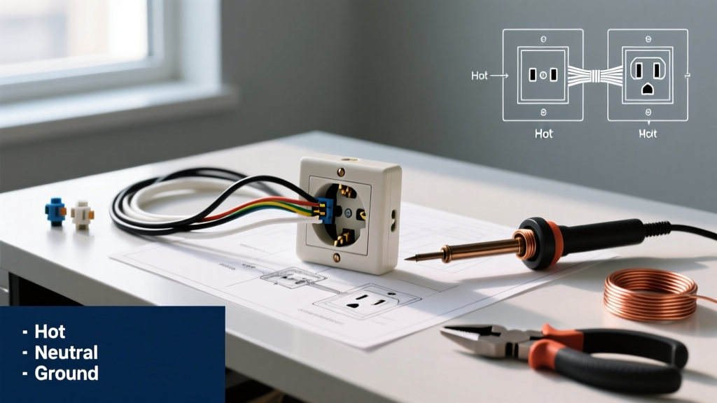
| Reversed Polarity | Black (hot) wire on silver screw; White (neutral) on brass screw. | Previous installer error; creates a shock hazard even when the device is switched off. Solution: Swap wires so black goes to brass (hot) and white goes to silver (neutral). |
Step 3: Wire Preparation and Proper Termination
If the existing receptacle is damaged, heavily scorched, or relies on backstabbed connections, it must be replaced. For standard residential applications, use a 15A Tamper-Resistant (TR) duplex receptacle, such as the Leviton T5262-E or the commercial-grade Eaton 8210W (20A). As of the 2023 and 2026 NEC cycles, TR receptacles are mandatory in almost all indoor dwelling unit locations to prevent children from inserting foreign objects.
The Side-Wiring Technique
Never use the push-in backstab holes on a new receptacle. Instead, use the side-wiring terminals or the internal screw-pressure plates found on higher-end commercial models.
- Strip the Wires: Use the built-in strip gauge on the back of the Leviton receptacle. For both 14 AWG (15A circuits) and 12 AWG (20A circuits), the exact strip length is typically 5/8 inch.
- Form the Hook: If using standard side screws, use needle-nose pliers to form a tight 'J-hook' in the bare copper.
- Orientation: Loop the wire clockwise around the screw. This ensures that as you tighten the screw (clockwise), the loop pulls tighter rather than pushing out from under the screw head.
- Torque: Tighten the terminal screw with your insulated torque screwdriver until it clicks at 14 in-lbs. This specific pressure ensures maximum surface contact without crushing the copper wire or stripping the brass threads.
Pigtailing for Continuous Circuits
If the outlet is in the middle of a run (meaning there are two black wires, two white wires, and two ground wires entering the box), do not daisy-chain the wires through the receptacle's internal brass strap. If the receptacle fails, it will kill power to everything downstream. Instead, use a pigtail. Connect the two incoming hot wires and a 6-inch black pigtail using a Wago 221-2 lever connector. Attach the single pigtail to the receptacle's brass screw. Repeat for the neutral and ground wires.
Step 4: Box Make-Up and Final Testing
Carefully fold the wires into the back of the junction box. The ground wires should go in first, pushed to the back left corner. Next, fold the white neutral wires, and finally the black hot wires. This 'Z-fold' method prevents pinching the hot wire against the metal box edge, which could cause a short circuit.
Mount the new receptacle using the provided 6-32 machine screws. Ensure the yoke sits flush against the drywall or plaster. If the box is recessed more than 1/4 inch from the wall surface, you must use plastic receptacle extenders (shims) to bring the yoke flush, as required by NEC 314.20. Attach the faceplate, restore power at the breaker, and test with a standard receptacle tester (like the Sperry ET6402) to confirm correct wiring, proper grounding, and TR functionality.
Edge Case: Multi-Wire Branch Circuits (MWBC)
If you open the box and find two black hot wires and two white neutral wires, but they are connected to different breakers that share a single neutral, you are dealing with an MWBC. Warning: You must turn off both breakers before touching any wires. If you break the shared neutral connection while one circuit is still live, you will create a 240V series circuit that will instantly destroy any electronics plugged into the downstream outlets. Always pigtail the neutral on an MWBC; never rely on the receptacle's internal strap to carry the neutral current.
Code Compliance Note: The Electrical Safety Foundation International (ESFI) strongly recommends upgrading all outdoor, bathroom, kitchen, and garage receptacles to GFCI (Ground Fault Circuit Interrupter) or AFCI (Arc Fault Circuit Interrupter) models if your main panel lacks these specific breaker protections. In 2026, AFCI protection is required in virtually all living spaces to mitigate parallel arc faults caused by damaged wire insulation.
Frequently Asked Questions
Why does my outlet have power but nothing works when plugged in?
This is almost always caused by a 'backstabbed' wire connection that has partially separated, or a broken internal brass strap. The NCVT will detect the voltage (phantom or real), but the moment a load is applied, the high-resistance connection drops the voltage to zero. Replacing the receptacle and using side-screw terminations will permanently resolve this.
Do I need a permit to replace a standard receptacle?
In most jurisdictions, a like-for-like replacement of an existing receptacle does not require a permit or an inspection. However, if you are adding a new junction box, running new cable, or upgrading a 2-prong ungrounded outlet to a 3-prong GFCI, local building codes may require a permit. Always check with your local Authority Having Jurisdiction (AHJ).
Can I put a 20A receptacle on a 15A breaker?
No. While the NEC allows a 15A receptacle on a 20A circuit (because standard 15A plugs are used on 20A circuits), it strictly prohibits installing a 20A receptacle (which features a T-shaped neutral slot) on a 15A breaker. The breaker would not trip before the receptacle's internal pathways are overloaded if a heavy 20A appliance is plugged in.