
Mastering the Basics of 6-Way Trailer Connections
Hooking up a utility trailer, boat trailer, or small camper in 2026 requires more than just a sturdy hitch; it demands a flawless electrical connection. While 4-pin connectors are common for light-duty hauling, medium-duty trailers with electric brakes or auxiliary 12V power requirements necessitate a 6-way setup. Understanding the correct wiring diagram for six pin trailer plug configurations is the difference between a safe highway journey and a dangerous roadside failure.
In this beginner installation tutorial, we will break down the exact pinouts, wire gauges, and step-by-step termination procedures required to build a reliable 6-pin trailer harness. We will also cover the most common failure modes—like ground loops and voltage drop—that plague first-time DIYers.
Identifying Your 6-Pin Configuration
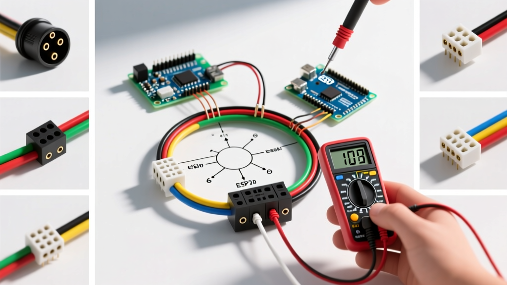
Before cutting any wire, you must identify which physical style of 6-pin connector your tow vehicle and trailer utilize. The two industry standards are:
- 6-Way Round Pin: Features six cylindrical metal pins. Common on heavy-duty utility, livestock, and commercial equipment trailers.
- 6-Way Flat Blade (Spade): Features flat, sliding blade connectors. Frequently found on boat trailers, RVs, and recreational campers.
Regardless of the physical shape, the internal electrical routing and color codes remain standardized by the RV Industry Association (RVIA) and the Society of Automotive Engineers (SAE). Always verify your vehicle's tow package output using a multimeter before assuming the factory wiring matches standard color codes, as some aftermarket harnesses deviate.
The Core Wiring Diagram for Six Pin Trailer Plug
The table below outlines the universal standard for 6-way trailer wiring. Pay close attention to the Wire Gauge (AWG) column. A critical mistake beginners make is using the same thin wire for every circuit. High-draw circuits like electric brakes and 12V auxiliary power require thicker wire to prevent voltage drop and overheating.
| Pin Position | Wire Color | Function | Minimum Wire Gauge |
|---|---|---|---|
| 1 (Ground) | White | Chassis Ground | 10 AWG |
| 2 (Tail) | Brown | Tail / Running / Marker Lights | 12 AWG |
| 3 (Left) | Yellow | Left Turn Signal & Stop Lamp | 12 AWG |
| 4 (Right) | Green | Right Turn Signal & Stop Lamp | 12 AWG |
| 5 (Brakes) | Blue | Electric Trailer Brakes | 10 AWG |
| 6 (Aux) | Black (or Red) | 12V Auxiliary / Battery Charge | 10 AWG |
Note: Compliance with federal lighting regulations, such as those outlined in FMCSA Part 393 Subpart B, mandates that all stop lamps and turn signals operate at specific candela levels. Using undersized wire causes voltage drop, resulting in dim lights that fail to meet federal safety standards.
Step-by-Step Beginner Installation Tutorial
Follow this precise workflow to terminate your 6-pin plug. Do not rush the stripping and crimping phases, as vibration and road moisture are the primary enemies of trailer wiring.
Step 1: Preparation and Stripping
Feed the main 6-conductor trailer cable through the rubber strain relief boot of the plug housing before stripping the wires. Use a dedicated wire stripper (like the Klein Tools 11063W) to remove exactly 3/8-inch of insulation from each wire. Stripping too much leaves exposed copper prone to shorting; stripping too little results in a weak crimp.
Step 2: Marine-Grade Crimping
Discard the cheap vinyl butt connectors included in most big-box store kits. Instead, use marine-grade heat shrink butt connectors (e.g., Ancor or Tinfoil brands). These feature a polyolefin heat shrink sleeve with an inner layer of hot-melt adhesive that creates a waterproof seal.
- Insert the stripped wire into the metal barrel of the connector.
- Use a ratcheting crimping tool (such as the IWISS IWS-16) to apply uniform pressure. A ratcheting tool ensures the crimp is fully compressed and will not pull out under the constant vibration of towing.
- Apply heat with a heat gun (not a lighter) until the adhesive oozes slightly from the ends.
Step 3: Terminal Insertion and Sealing
Before screwing the wires into the terminal block or soldering them to the pins, apply a small dab of dielectric grease (like Permatex 22058) to the metal contact points. This prevents galvanic corrosion, which is especially critical for boat trailers exposed to saltwater or utility trailers treated with road salt in winter.
Step 4: Pre-Assembly Testing
Before snapping the plug housing shut, connect the plug to your tow vehicle. Use a digital multimeter or a dedicated trailer tester (like the Tow Ready 20117) to verify each circuit. Have a helper press the brake pedal and activate the turn signals while you confirm voltage at the corresponding pins.
Critical Troubleshooting: Ground Loops and Voltage Drop
Even with a perfect wiring diagram for six pin trailer plug setups, environmental factors can cause electrical gremlins. Here is how to diagnose the two most common issues:
The Ground Loop Trap: If your trailer's turn signals cause the brake lights to dim, or if the running lights flicker when you hit the brakes, you have a ground loop. This happens when the 10 AWG white ground wire is insufficient, forcing the electrical current to seek an alternative path back to the vehicle—often through the hitch ball and safety chains. The Fix: Run a dedicated 10 AWG white wire directly from the plug's ground pin to a clean, bare-metal spot on the trailer frame, and run secondary ground pigtails from every individual trailer light directly to the frame.
Understanding Voltage Drop on Electric Brakes
Electric trailer brake magnets draw significant current (often 3 to 4 amps per wheel). If you use 14 AWG or 16 AWG wire for the blue brake circuit over a 25-foot trailer tongue, you will experience severe voltage drop. According to Ohm's Law, this resistance reduces the voltage reaching the brake magnets, resulting in weak, delayed braking. Always use 10 AWG wire for the blue brake circuit, and ensure your brake controller is properly calibrated to the trailer's gross vehicle weight rating (GVWR).
Upgrading from a 4-Pin to a 6-Pin System
Many beginners start with a 4-pin flat connector and later add electric brakes or a winch battery, requiring an upgrade to a 6-pin. You have two options:
- The Adapter Route: Using a 4-pin to 6-pin adapter (like the Tow Ready 47435) is a quick fix, but it does not provide the heavy-duty 10 AWG wiring needed for electric brakes. The adapter merely splits the existing 4-pin circuits and leaves the brake and aux pins dead unless you run separate, external wires from the engine bay.
- The Hardwire Route (Recommended): Remove the 4-pin entirely. Install a dedicated 6-way socket on your vehicle's bumper and run a new, continuous 10 AWG loom from the vehicle's front battery and brake controller directly to the rear socket. For detailed vehicle-side routing techniques, consult eTrailer's comprehensive wiring FAQ to find model-specific routing diagrams for your truck or SUV.
Essential 2026 Tool & Material Checklist
To execute this tutorial professionally, ensure your workbench is stocked with the following specific items. Prices reflect average 2026 retail estimates:
- Ratcheting Wire Crimper: IWISS IWS-16 or Titan 11110 ($35 - $50). Essential for gas-tight crimps.
- Marine Heat Shrink Connectors: Ancor Marine Grade 12-10 AWG Assortment ($25). Do not substitute with standard vinyl.
- Digital Multimeter: AstroAI DM6000AR or Fluke 117 ($40 - $200). Required for verifying continuity and voltage drop.
- Dielectric Grease: Permatex 22058 Dielectric Tune-Up Grease ($8). Crucial for preventing green corrosion on copper terminals.
- Trailer Tester: Hopkins 47995 or Tow Ready 20117 ($15). Allows you to simulate vehicle signals without needing a second person in the driver's seat.
Final Safety Verification
Once your wiring diagram for six pin trailer plug is fully executed and the housing is sealed, perform a final physical tug-test on every wire. The strain relief boot on the plug housing should absorb all pulling forces, not the terminal screws. Finally, secure the trailer harness to the tongue using UV-resistant zip ties or split loom tubing every 12 inches to prevent the wires from chafing against the steel frame during tight turns. Safe towing starts with a bulletproof electrical connection.