
The Critical Role of Post-Installation Verification
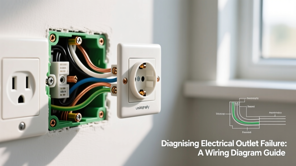
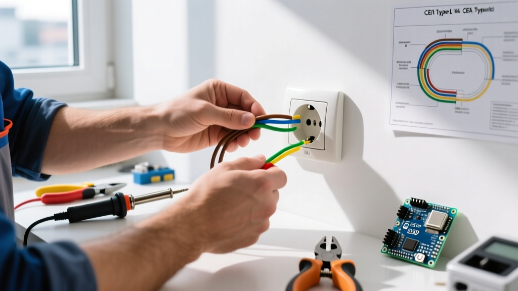
Completing the physical wiring of a receptacle is only half the battle. A proper electrical outlet installation requires rigorous post-wiring inspection and live-circuit testing to ensure compliance with the National Electrical Code (NEC) and to guarantee long-term operational safety. In 2026, with the widespread adoption of smart home ecosystems and higher continuous loads from modern electronics, the tolerance for high-resistance connections or improper grounding is virtually zero. This guide provides a master-class workflow for inspecting and testing your newly installed outlets, moving from dead-circuit mechanical verification to advanced live-circuit diagnostics.
⚠️ SAFETY WARNING: Never proceed to Phase 2 (Live Testing) until all Phase 1 (Pre-Power) mechanical inspections are complete. Ensure your circuit breaker is locked out and tagged out (LOTO) during the visual inspection phase. Always verify the circuit is dead with a non-contact voltage tester (NCVT) before touching any bare conductors.
Essential Tool Loadout for 2026
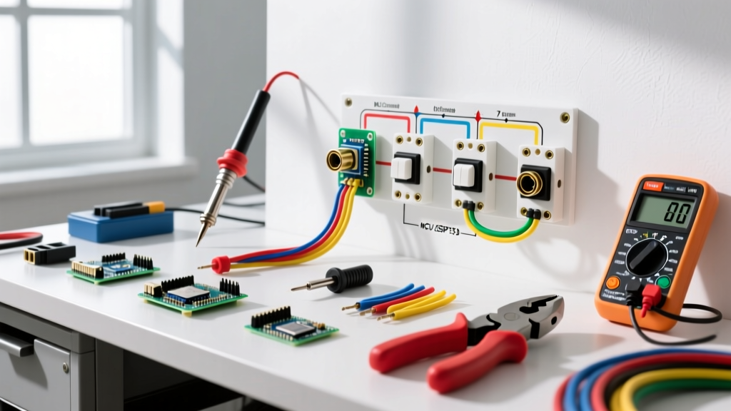
Accurate diagnostics require precision instruments. Relying on a $10 multimeter from a hardware store bin will not reveal high-resistance faults or microsecond GFCI trip failures. Equip yourself with the following professional-grade tools:
- Torque Screwdriver: The Klein Tools 32307 (approx. $150) or Wiha 28501. NEC Article 110.14(D) strictly mandates that terminations be torqued to manufacturer specifications.
- True-RMS Digital Multimeter: The Fluke 117 Electricians True RMS Multimeter (approx. $210) features VoltAlert non-contact voltage detection and low-impedance (LoZ) mode to eliminate ghost voltage readings.
- Advanced Receptacle Tester: The Klein Tools RT250 (approx. $45) goes beyond basic LED patterns by providing an LCD screen that explicitly identifies wiring faults and tests GFCI trip times.
- Thermal Imaging Camera: The FLIR C5 (approx. $500) is invaluable for scanning loaded receptacles to detect heat buildup caused by loose terminations.
Phase 1: Pre-Power Visual and Mechanical Inspection
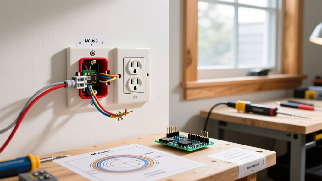
Before restoring power, you must validate the physical integrity of the installation. Pushing wires haphazardly into a crowded junction box is a leading cause of arc faults and thermal failures.
1. Box Fill Capacity Verification
Overcrowded boxes trap heat and damage wire insulation. Referencing NFPA 70 (NEC) Article 314.16, calculate your box fill. For standard 12 AWG copper wire, each conductor requires 2.25 cubic inches of volume. A standard single-gang deep box (22.5 cu in) can comfortably hold a duplex receptacle and up to four 12 AWG current-carrying conductors. If you are pigtailing grounds and neutrals, ensure the internal clamp and device yoke allowances are factored in.
2. Torque Specification Compliance
Hand-tightening terminal screws is a code violation and a fire hazard. Under-torqued screws loosen over time due to thermal expansion and contraction (thermal ratcheting), creating high-resistance arcing points. Over-torqued screws strip threads or shear the conductor.
| Wire Gauge | Wire Type | Typical Torque Range | Common Application |
|---|---|---|---|
| 14 AWG | Solid Copper | 12 - 14 in-lbs | 15A Lighting/Bedroom Circuits |
| 12 AWG | Solid Copper | 14 - 16 in-lbs | 20A Kitchen/Bathroom Circuits |
| 10 AWG | Solid/Stranded | 20 - 25 in-lbs | 30A Specialty Equipment |
3. Termination Method Audit
Inspect how the wires are secured. Backstab (push-in) connections on 15A receptacles are notorious for failing under heavy loads and are banned in many commercial jurisdictions. For residential electrical outlet installation, always use the side-wire screw terminal method or the screw-clamp plates found on premium commercial-grade receptacles like the Hubbell HBL5262. Ensure no bare copper is exposed outside the terminal saddle, and that the wire insulation is not pinched under the screw head.
Phase 2: Live Circuit Testing & Verification
Once the receptacle is mounted, the cover plate is installed, and the breaker is energized, it is time to verify the electrical characteristics of the circuit.
Interpreting Receptacle Tester Readings
Plug your advanced tester (e.g., Klein RT250) into the top and bottom receptacles. Do not assume that if the top outlet is wired correctly, the bottom one is too; internal brass tabs may have been broken incorrectly during a multi-wire branch circuit (MWBC) installation.
| Displayed Fault | Probable Cause | Required Corrective Action |
|---|---|---|
| Open Ground | Missing equipment grounding conductor (EGC) or loose connection at the panel. | Trace EGC back to the panel; verify bonding. Do NOT use a bootleg ground. |
| Hot/Neutral Reverse | Black (hot) and White (neutral) wires swapped on the receptacle terminals. | De-energize and swap wires. Brass screw = Hot, Silver screw = Neutral. |
| Hot/Ground Reverse | Severe miswiring; ground wire is energized. | Immediate shutdown. Check for crossed wires at the panel or upstream junction. |
| Open Neutral | Neutral wire disconnected or broken upstream. | Check wire nuts and backstab connections upstream. |
Multimeter Voltage Drop and Ground Integrity Testing
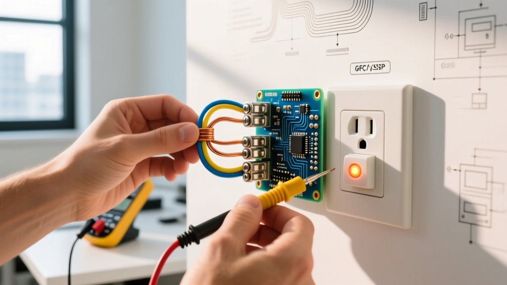
A basic plug-in tester cannot detect a "bootleg ground" (a jumper wire illegally connecting the neutral terminal to the ground screw to trick inspectors). To verify a true earth ground, use your True-RMS multimeter:
- Hot to Neutral: Should read between 114V and 126V.
- Hot to Ground: Should read within 1-2V of the Hot-to-Neutral reading.
- Neutral to Ground: Should read less than 2V. If it reads exactly 0.0V under load, or if Hot-to-Ground reads 0V while Hot-to-Neutral reads 120V, you have a missing or bootlegged ground.
Advanced Diagnostics: GFCI, AFCI, and TR Receptacles
Modern electrical codes require advanced protection in specific zones. Testing these devices requires specific protocols.
GFCI Trip Time and Threshold Testing
According to the Electrical Safety Foundation International (ESFI), Ground Fault Circuit Interrupters are designed to protect against lethal shock by detecting current imbalances as small as 4 to 6 milliamps. Using the test button on the receptacle face only verifies the mechanical trip mechanism; it does not verify the electronic trip threshold or timing. Use a dedicated GFCI tester to inject a precise 6mA fault. The receptacle must trip in under 25 milliseconds. If it takes longer, or fails to trip, the internal solenoid is degraded and the device must be replaced.
Tamper-Resistant (TR) Shutter Verification
NEC Article 406.12 mandates TR receptacles in all dwelling unit areas. The internal shutters prevent foreign objects from contacting energized parts. To test the shutters during inspection, do not use a paperclip or a single probe, which will jam the mechanism. Instead, use a standard 14 AWG solid copper wire or a two-prong plug to apply simultaneous, equal pressure to both the hot and neutral slots. The shutters should open smoothly without excessive force.
Common Installation Failure Modes & Edge Cases
Even experienced electricians can fall victim to subtle installation errors. Be on the lookout for these specific edge cases:
- Shared Neutral on MWBC without Handle Tie: If you are installing an outlet on a Multi-Wire Branch Circuit, the two hot breakers must have an identified handle tie (NEC 210.4). Failing to do this means a worker could turn off one breaker, assume the neutral is dead, and suffer a fatal shock from the return current of the other active phase.
- Pigtail Failure in Daisy Chains: When wiring multiple outlets in series, the neutral and hot must be pigtailed using wire nuts or Wago lever connectors (like the Wago 221-413). Breaking the downstream circuit by removing a single receptacle is a major code violation and safety hazard.
- Drywall Pinching: If the drywall cutout is too tight, it can press against the side wiring terminals, potentially cracking the insulation or pushing a loose wire out of the terminal saddle. Always ensure a minimum 1/4 inch clearance around the device yoke.
Frequently Asked Questions (FAQ)
Why does my new outlet spark when I plug in a vacuum or power tool?
A small, brief blue spark is normal when plugging in high-inductive loads (like vacuum motors) because the motor draws a massive inrush current the millisecond the contacts bridge. However, if the spark is large, yellow/orange, or accompanied by a popping sound and melted plastic smell, you likely have a loose internal connection or a failing terminal. Unplug the device immediately and perform a thermal scan.
Can I use a standard receptacle tester on a 20A circuit?
Yes, standard 15A plug-in testers will physically fit into a 20A receptacle (which has a T-shaped neutral slot to accept both 15A and 20A plugs) and will accurately read the wiring topology. However, the tester will not verify the 20A breaker sizing or the 12 AWG wire gauge; you must verify those visually at the panel and the termination point.
What is the acceptable voltage drop for a long outlet run?
The NEC recommends a maximum voltage drop of 3% for branch circuits. On a 120V circuit, this means the voltage at the furthest outlet under full load should not drop below 116.4V. If you measure 110V under load at the end of a 100-foot run, you must upgrade the wire from 14 AWG to 12 AWG, or from 12 AWG to 10 AWG, to reduce resistance and prevent overheating.
For more comprehensive safety standards regarding residential wiring and shock prevention, always consult the latest guidelines published by the U.S. Consumer Product Safety Commission (CPSC). A meticulous electrical outlet installation is defined not by how fast it is wired, but by how rigorously it is tested.