
The Hidden Dangers of a Failing Receptacle
A faulty electrical outlet is rarely just a minor inconvenience; it is a primary ignition point for residential electrical fires. According to the Occupational Safety and Health Administration (OSHA), electrical system failures, including degraded receptacles and loose terminal connections, account for thousands of structural fires annually. As of the 2026 National Electrical Code (NEC) updates, the tolerance for aging, non-compliant, or physically degraded wiring devices has effectively reached zero. Homeowners and DIYers must approach outlet troubleshooting with a methodical, data-driven strategy rather than relying on guesswork.
This expert guide walks you through the precise diagnostic sequence for identifying a failing receptacle, from initial visual triage to advanced digital multimeter analysis. We will cover exact voltage tolerances, specific failure modes like backstab degradation, and the precise replacement protocols required by modern electrical codes.
Phase 1: Visual and Physical Triage (No Tools Required)
Before introducing any testing equipment, conduct a rigorous physical inspection. Many critical failure modes present obvious physical symptoms that dictate immediate replacement.
- The Plug Retention Test: Insert a standard 15-amp NEMA 5-15 plug into the top and bottom receptacles. If the plug slides in with zero resistance or falls out under its own weight, the internal brass contact springs have permanently deformed. This creates a high-resistance connection that generates excessive heat under load.
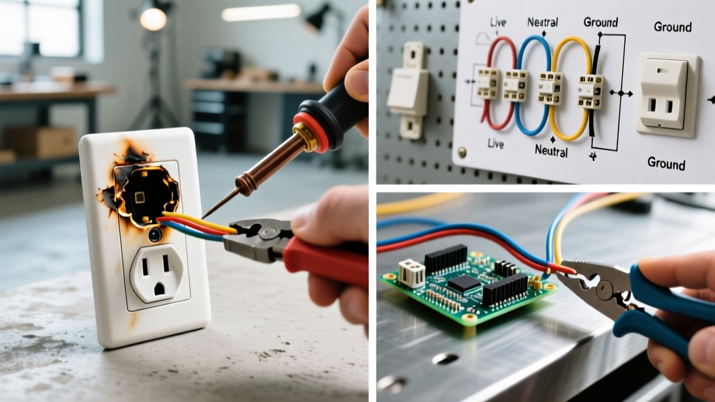
- Thermal Discoloration: Inspect the thermoplastic face of the outlet. Yellowing, browning, or black scorch marks around the hot (short) slot indicate historical arcing or overheating. According to the Consumer Product Safety Commission (CPSC), any sign of thermal degradation warrants immediate circuit shutdown and device replacement.
- Faceplate Warping: A cracked or bulging faceplate often indicates that the underlying yoke has been overtightened against an uneven drywall cutout, stressing the internal contacts, or that heat from a high-draw appliance has warped the plastic.
Phase 2: The Receptacle Tester Diagnostic Matrix
For quick, non-invasive diagnostics, a 3-light receptacle tester (such as the Klein Tools RT250 or Gardner Bender GRT-501) is your first line of defense. While these tools do not measure exact voltage, they instantly identify critical wiring topology errors.
| Wiring Condition | Left Light (Yellow) | Center Light (Yellow) | Right Light (Red/Off) | Diagnostic Meaning & Action |
|---|---|---|---|---|
| Correct Wiring | ON | ON | OFF | Circuit is wired correctly. Proceed to voltage testing. |
| Open Hot | OFF | ON | ON | No power on the hot wire. Check upstream GFCI or breaker. |
| Open Neutral | ON | OFF | OFF | Return path is broken. Inspect neutral wire nuts and backstabs. |
| Hot/Neutral Reversed | ON | ON | ON | Polarity is swapped. Dangerous; devices remain energized when off. |
| Hot/Ground Reversed | Red ON | Yellow ON | OFF | Bootleg ground or severe miswire. Do not use; call an electrician. |
Phase 3: Advanced Multimeter Troubleshooting
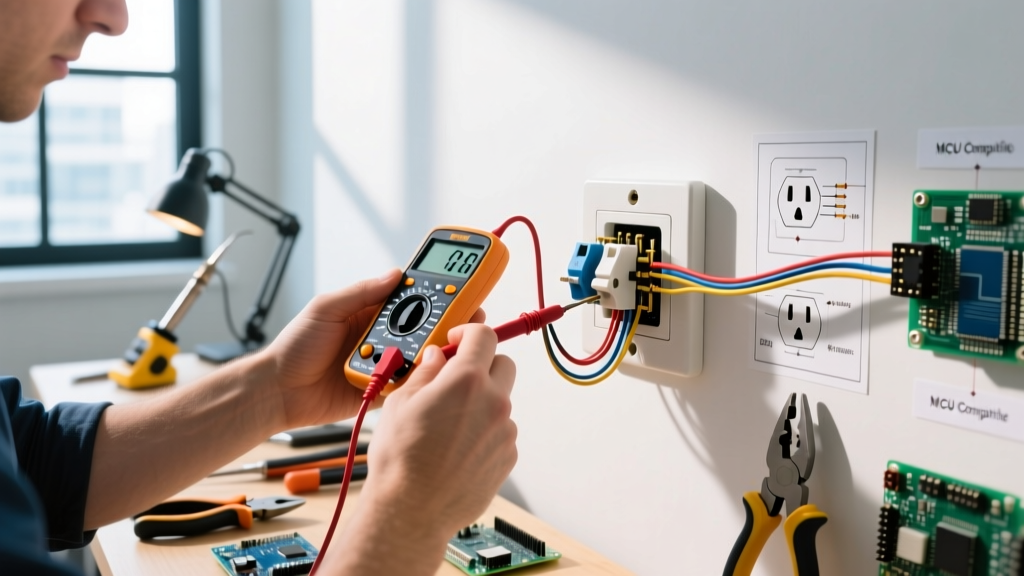
When a receptacle passes the physical and 3-light tests but appliances still fail to operate or trip breakers, you must measure actual electrical potential. Use a True-RMS digital multimeter, such as the Fluke 117 or Klein Tools MM400, to capture accurate readings even on non-linear loads.
Step-by-Step Voltage Verification
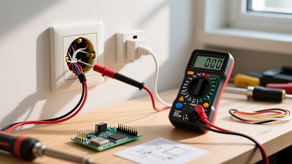
- Set the Multimeter: Turn the dial to AC Voltage (V~) and select a range above 150V (or auto-ranging).
- Hot to Neutral (H-N): Insert the black probe into the neutral (long) slot and the red probe into the hot (short) slot. Per ANSI C84.1 standards, a standard US residential circuit should read between 114V and 126V. A reading below 110V indicates excessive voltage drop, likely caused by a loose connection upstream or undersized wiring (e.g., 14 AWG wire on a 50-foot run carrying 14 amps).
- Hot to Ground (H-G): Move the black probe to the U-shaped ground slot. The reading should be nearly identical to H-N (within 1-2 volts). If H-G reads significantly lower than H-N, you have a high-resistance ground path or a shared neutral issue.
- Neutral to Ground (N-G): Measure between the neutral and ground slots. This should read as close to 0V as possible (typically 0.5V to 2.0V is acceptable due to normal line impedance). A reading above 5V indicates a loose neutral connection somewhere on the circuit, causing neutral current to seek a path through the grounding system.
Expert Insight: The Phantom Voltage Trap
If your multimeter reads 40V to 80V on a dead outlet, do not assume the circuit is live. Digital multimeters have high input impedance (typically 10 Megohms) and can pick up 'phantom voltage' induced by adjacent live wires in the same cable sheath. Press the 'LoZ' (Low Impedance) button on your Fluke 117 to shunt this ghost voltage and confirm the circuit is truly dead.
Phase 4: Uncovering Hidden Failure Modes
If your tests confirm a faulty electrical outlet, the root cause usually lies behind the drywall. Understanding these specific failure modes will dictate your repair strategy.
1. Backstab (Push-In) Terminal Degradation
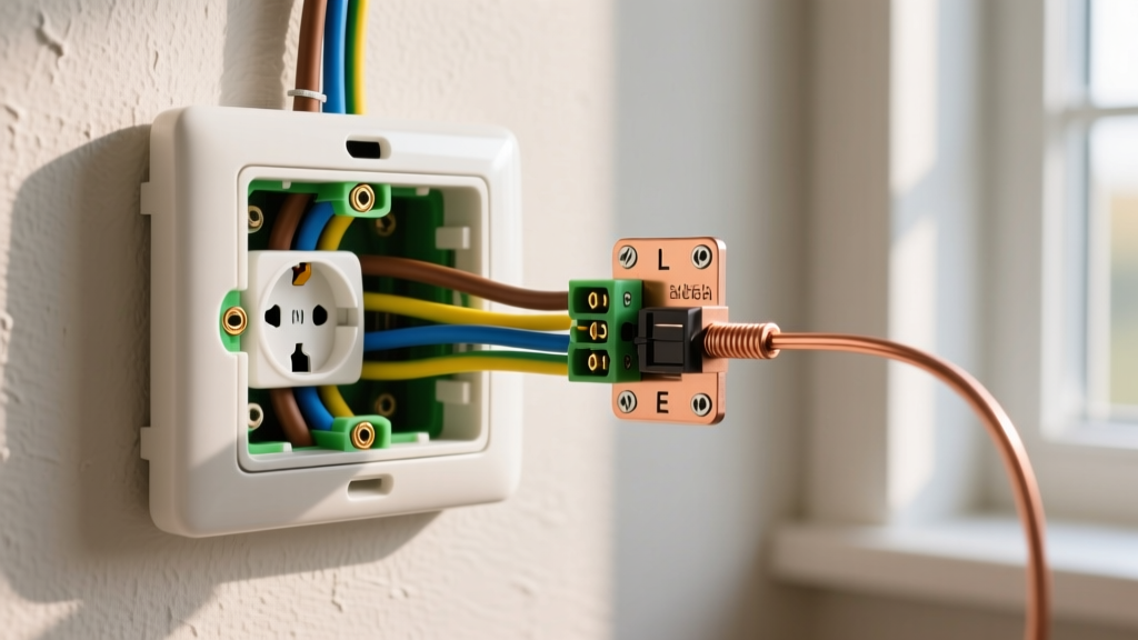
Many builder-grade receptacles utilize push-in 'backstab' connectors rather than screw terminals. These rely on a tiny internal brass spring to grip the 14 AWG copper wire. Over years of thermal cycling (heating under load, cooling when idle), this spring loses tension. The resulting micro-arcing creates carbon buildup, increasing resistance and causing downstream outlets to lose power. Solution: Never reuse backstab connections. Strip 3/4 inch of insulation and loop the wire clockwise around the side terminal screw.
2. Aluminum Wiring Oxidation
Homes built between 1965 and 1972 often feature aluminum branch circuit wiring. Aluminum oxidizes rapidly when exposed to air and expands/contracts more than copper, loosening terminal screws over time. If you diagnose a faulty outlet in an aluminum-wired home, standard copper-rated receptacles are illegal and dangerous. You must use CO/ALR rated receptacles (like the Leviton 1215) or pigtail the aluminum to copper using AlumiConn lug connectors before terminating at a standard device.
3. Daisy-Chain Cascading Failures
Residential circuits are typically wired in a daisy-chain topology. If an outlet in the middle of the chain relies on its own terminal screws to pass power to the next outlet, a loose wire on the current device will kill power to everything downstream. Best Practice: Use a wire nut (e.g., Ideal 30-102) or a push-in wire connector (e.g., Wago 221-413) to splice the incoming and outgoing wires together, attaching only a single pigtail to the receptacle itself. This ensures downstream continuity even if the receptacle is removed.
Phase 5: NEC 2026 Compliance and Replacement Protocols
When replacing a diagnosed faulty receptacle, you cannot simply swap it for any generic device on the shelf. The National Fire Protection Association (NFPA) mandates strict adherence to the current NEC for all replacements.
- Tamper-Resistant (TR) Requirement: Per NEC Article 406.4(D), all 15A and 20A, 125V and 250V non-locking receptacles in dwelling units must be Tamper-Resistant. Look for the 'TR' stamp on the yoke (e.g., Leviton T5325-W). These feature internal shutters that prevent children from inserting single conductive objects.
- Precision Torque: The NEC now requires terminal screws to be tightened to the manufacturer's specified torque. For standard 15A receptacles, this is typically 14 in-lbs. Use a dedicated torque screwdriver (like the Klein Tools 32500) to prevent under-tightening (which causes arcing) or over-tightening (which strips the brass threads or crushes the wire).
- GFCI Upgrades: If the faulty outlet is located in a kitchen, bathroom, garage, or within 6 feet of a water source, it must be replaced with a Ground Fault Circuit Interrupter (GFCI). Modern self-testing GFCIs, such as the Leviton AFGF1-W (approx. $28 in 2026), continuously monitor for ground faults and will lock out if internal components degrade.
Frequently Asked Questions (FAQ)
Why does my outlet work intermittently when I wiggle the plug?
This is the hallmark of worn internal contact springs or a failing backstab connection. The physical movement temporarily bridges the high-resistance gap. This is an extreme fire hazard; stop using the outlet immediately, turn off the breaker, and replace the receptacle.
My receptacle tester says 'Open Neutral', but all the wires look connected. Why?
An 'Open Neutral' reading doesn't always mean the neutral wire fell off the specific outlet you are testing. Because circuits are daisy-chained, a loose neutral wire nut at the previous outlet on the circuit, or a broken neutral bus bar in the main panel, will yield the exact same reading. Trace the circuit backward from the panel.
Can a faulty outlet trip a GFCI breaker in the main panel?
Yes. If the outlet has internal insulation breakdown, moisture ingress, or a pinched wire behind the yoke allowing micro-amps of current to leak to the ground wire, a highly sensitive AFCI/GFCI combo breaker (which trips at 5mA for ground faults or detects parallel arcing signatures) will shut down the entire circuit to prevent shock or fire.