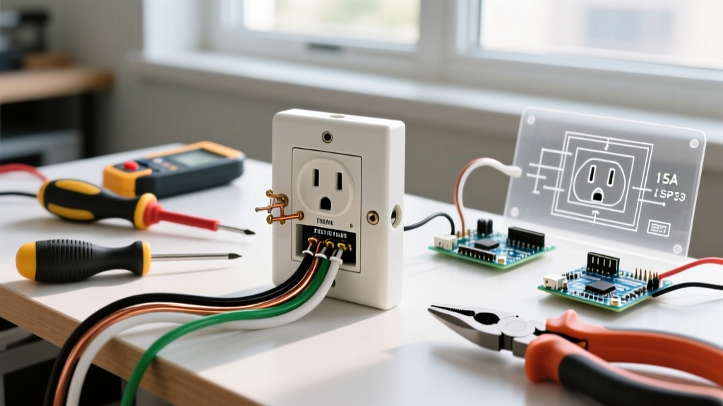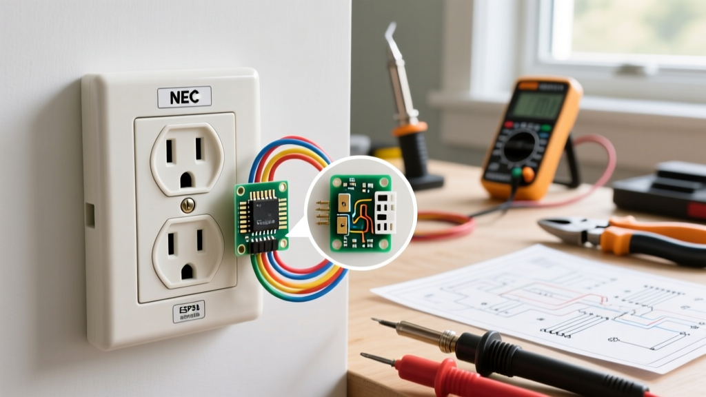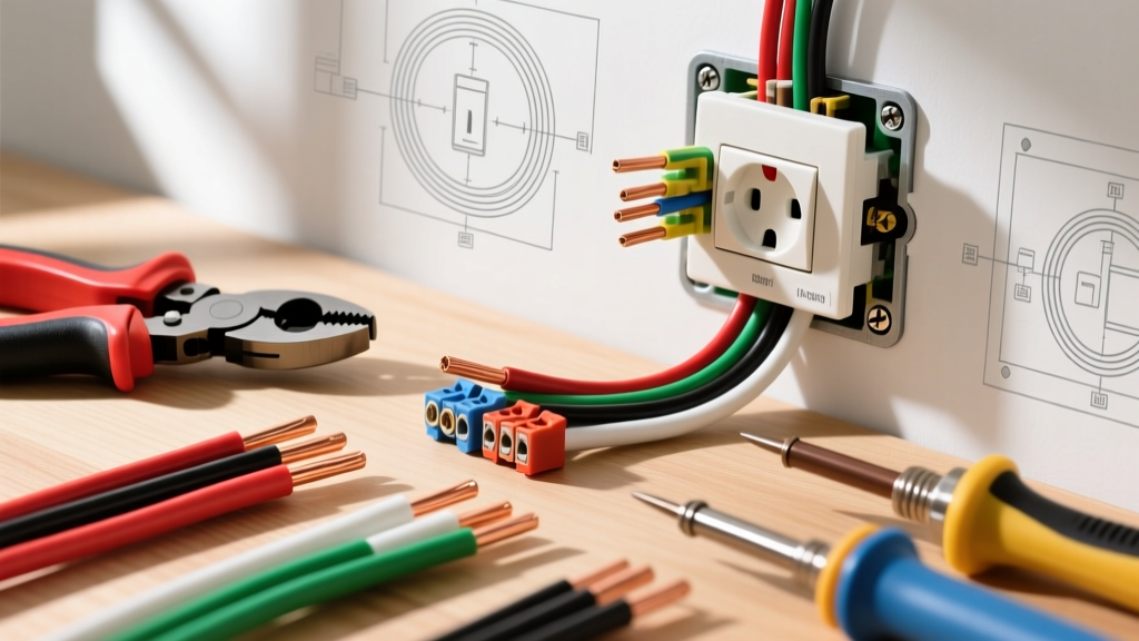

The Foundation of Safe Wiring: Choosing the Correct Gauge
When planning a branch circuit, selecting the proper electric wire for outlet receptacles is not just a matter of convenience—it is a strict requirement under the National Electrical Code (NEC). As of the 2026 adoption cycles, local inspectors are heavily scrutinizing wire-to-breaker sizing, box fill calculations, and termination torque. Using undersized wire creates a severe fire hazard due to resistive heating, while oversized wire can fail to seat properly in standard 15A or 20A terminal clamps.
According to the National Fire Protection Association (NFPA), which publishes the NEC, mismatched wire gauges and overcurrent protection devices are a leading cause of residential electrical fires. This guide breaks down exactly how to choose, prep, and terminate the right cable for your receptacles.
Wire Gauge and Breaker Sizing Matrix
Before pulling any cable, you must match the wire gauge (AWG) to the circuit breaker and the receptacle rating. The table below outlines the standard non-metallic (NM-B) sheathed cable configurations used in modern residential construction.
| Wire Gauge (AWG) | Breaker Size | Max Load (120V) | Jacket Color (NM-B) | Typical Application |
|---|---|---|---|---|
| 14 AWG (14/2) | 15 Amp | 1,800 Watts | White | Standard bedroom/living room lighting and general-use 15A outlets. |
| 12 AWG (12/2) | 20 Amp | 2,400 Watts | Yellow | Kitchen small-appliance circuits, bathroom GFCI outlets, and garage receptacles. |
| 10 AWG (10/2) | 30 Amp | 3,600 Watts | Orange | Heavy appliances (dryers, water heaters). Not used for standard 120V 15A/20A duplex outlets. |
2026 Pro Tip: While 14 AWG is legal for 15A circuits, many professional electricians exclusively use 12 AWG (yellow jacket) for all general-purpose outlet circuits. The marginal increase in material cost (roughly $0.12 more per foot in 2026) provides a 33% increase in current capacity and significantly reduces voltage drop on long runs.
Tools and Materials for the Job
Professional results require professional tools. Do not rely on cheap, multi-purpose utility knives for stripping wire, as nicking the copper conductor creates a localized hot spot that can lead to arcing and failure.
- Wire: Southwire 250-ft 12/2 NM-B (Approx. $115 - $135 per roll).
- Strippers: Klein Tools 11055 Wire Stripper ($28) for clean, precise insulation removal.
- Tester: Milwaukee 2202-20 Non-Contact Voltage Tester ($35).
- Torque Screwdriver: Klein Tools 3271 or similar calibrated to 14 in-lbs.
- Connectors: Ideal 33-091 Twist-On Wire Nuts or Wago 221 Series Lever-Nuts for pigtailing.
- Receptacles: Tamper-Resistant (TR) Duplex Receptacles (e.g., Leviton 5320-W or Eaton TR270W).
Step-by-Step Installation Guide
Step 1: Power Down and Verify
Locate the main service panel and switch off the breaker controlling the circuit. Place a piece of electrical tape over the breaker to prevent accidental re-engagement. Use your non-contact voltage tester at the existing outlet and at the panel to confirm zero voltage. The Occupational Safety and Health Administration (OSHA) mandates a 'Test Before Touch' protocol for all electrical work to prevent arc flash and electrocution hazards.
Step 2: Routing and Prepping the Electric Wire
Feed the NM-B cable through the framing studs and into the electrical box. Ensure the cable is secured with a staple within 8 inches of the box, as per NEC Article 334.30.
- Set the Jacket: The outer plastic jacket of the NM-B cable must enter the box by at least 1/4 inch to protect the inner conductors from the sharp metal or plastic edges of the box knockout.
- Determine Slack: Leave exactly 6 to 8 inches of individual wire slack extending past the face of the box. Too little slack makes termination impossible; too much creates a box-fill violation.
- Strip the Insulation: Using your Klein Tools strippers, remove exactly 3/4 inch of insulation from the black (hot) and white (neutral) wires. If you can see bare copper between the terminal pad and the insulation when seated, you have stripped too much, creating a shock hazard.
Step 3: Termination and Torque Specifications
How you connect the electric wire for outlet terminals dictates the longevity of the circuit. There are two acceptable methods for modern TR receptacles:
- Side-Wiring (Shepherd Hook): Loop the bare copper clockwise around the terminal screw. The clockwise direction ensures that tightening the screw pulls the loop tighter, rather than pushing it out.
- Back-Wiring (Clamp Plate): Insert the straight, stripped wire into the back hole and tighten the screw. Note: This refers to premium receptacles with internal screw-down clamp plates, NOT the cheap 'push-in' stab connections found on builder-grade outlets, which are notorious for failing under heavy loads.
The Torque Requirement: As of recent NEC updates, listed torque values must be followed. For standard 15A and 20A residential receptacles, the terminal screws typically require 14 in-lbs of torque. Under-torquing leads to thermal expansion and contraction cycles that loosen the connection over time, causing arcing. Over-torquing can strip the brass threads or damage the copper wire.
Step 4: Grounding and Box Packing
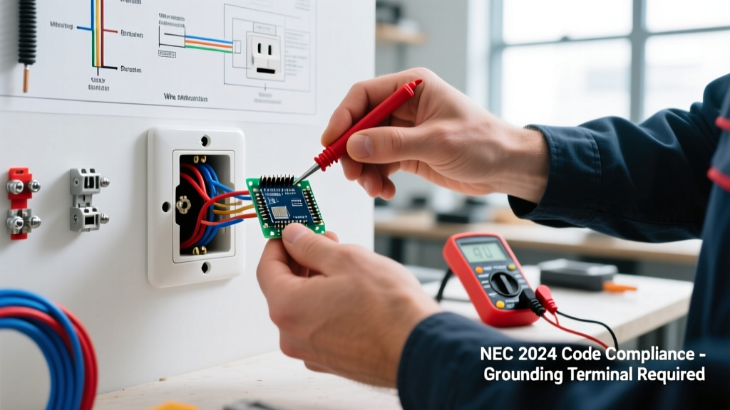
Connect the bare copper ground wire to the green grounding screw on the receptacle. If you are using a metal electrical box, you must also bond the box using a grounding pigtail attached to the internal grounding clip or a 10-32 grounding screw. Once all connections are made and verified with a gentle tug test, carefully fold the wires into the box in a 'Z' pattern (ground in back, neutral in middle, hot in front) to avoid pinching the insulation against the metal yoke of the outlet.
Advanced Edge Cases and Troubleshooting
Voltage Drop on Long Runs
If your circuit run from the panel to the furthest outlet exceeds 75 feet, standard 12 AWG wire may experience a voltage drop exceeding the recommended 3% limit under full load. In these scenarios, you must upsize the electric wire for outlet feeds to 10 AWG to compensate for resistance. However, because 10 AWG wire will not physically fit under the terminal screws of a standard 20A receptacle, you must use a 12 AWG pigtail (using a Wago lever-nut or wire nut) inside the box to make the final connection to the device.
Multi-Wire Branch Circuits (MWBC)
When wiring kitchen outlets, you may encounter a 12/3 NM-B cable (black, red, white, bare) feeding a split-receptacle. This is a Multi-Wire Branch Circuit. The critical safety rule here is that the white neutral wire carries the unbalanced load. If you ever disconnect the neutral wire while the circuit is live, the return path is broken, and the devices on the opposing phase will be subjected to 240V, instantly destroying appliances and creating a massive fire hazard. Always use handle-ties on the two breakers supplying an MWBC to ensure simultaneous disconnect.
Frequently Asked Questions
Can I use 12 AWG wire on a 15 Amp breaker?
Yes. The NEC allows using a larger wire gauge than the minimum required for a specific breaker size. A 15A breaker will perfectly protect a 12 AWG wire, and this is a common practice for future-proofing circuits.
Is it safe to use aluminum wire for standard outlets?
No. Modern residential branch circuits for 15A and 20A outlets exclusively use solid copper wire. Aluminum wire is generally reserved for heavy feeder cables (like 2/0 AWG for main service panels) and requires specialized antioxidant paste and CO/ALR rated terminals, which standard duplex receptacles do not possess.
Why did my outlet melt at the wire connection?
According to data from the Consumer Product Safety Commission (CPSC), melted terminals are almost always caused by a loose connection rather than an overloaded circuit. A loose screw creates high electrical resistance at the termination point, generating intense, localized heat that melts the plastic face of the receptacle. This is why using a calibrated torque screwdriver is non-negotiable for modern electricians.
Final Inspection Checklist
Before restoring power, verify the following:
- No bare copper is visible outside the terminal clamps.
- The ground wire is securely bonded to both the device and the box (if metal).
- All wire nuts or lever-connectors are tight, with no exposed copper at the base.
- The receptacle is mounted flush to the wall plate without cracking the plastic yoke from over-tightening.
By strictly adhering to these wire sizing rules and termination practices, you ensure a robust, fire-resistant electrical system that will safely serve your home for decades.