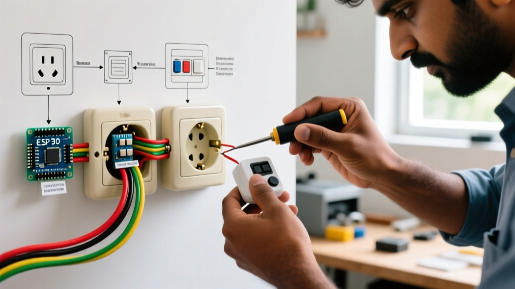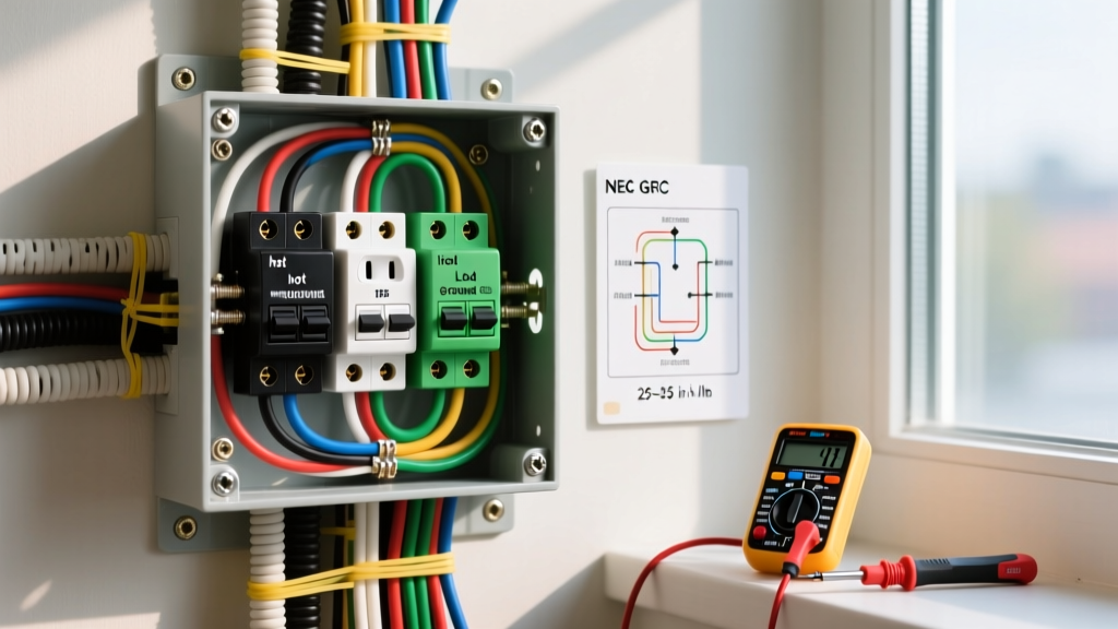

Understanding Single Pole Electrical Switch Wiring
For DIY beginners, electrical switch wiring can seem intimidating, but the single pole switch is the most straightforward circuit in residential wiring. A single pole switch controls a light or appliance from one location. Unlike complex 3-way or 4-way setups, a single pole circuit relies on a simple "make and break" mechanism on the hot (line) wire, leaving the neutral wire completely uninterrupted.
According to the National Fire Protection Association (NFPA), adhering to the National Electrical Code (NEC) is mandatory for safety and insurance compliance. In 2026, the NEC continues to enforce strict rules on box fill capacity, grounding, and the use of AFCI/GFCI protection in specific rooms. This tutorial focuses on replacing or installing a standard 15-amp single pole toggle or rocker switch in an existing, code-compliant junction box.
Essential Tools and Material Costs
Before cutting any wires, gather the proper tools. Using the right equipment prevents damaged screw terminals and ensures a secure connection that won't arc over time.
- Non-Contact Voltage Tester: Klein Tools NCVT-2 (Approx. $22) - Crucial for verifying dead circuits.
- Wire Strippers: Klein Tools 11063W (Approx. $28) - For cleanly stripping 14 and 12 AWG solid copper.
- Screwdrivers: #1 and #2 Phillips, plus a 1/8-inch flathead.
- Needle-Nose Pliers: For forming precise wire hooks.
- The Switch: Leviton Decora 15A Single Pole (Model R62-05601) or Eaton 15A Toggle (Approx. $2 to $5 each).
Total estimated cost for a basic replacement: Under $35 if you already own the hand tools.
Step-by-Step Installation Procedure
Step 1: Kill the Power and Verify
Locate your main electrical panel and turn off the breaker controlling the room. Never rely solely on the wall switch being in the "off" position. Use your non-contact voltage tester on the switch plate screws, then remove the plate and test the wires inside the box. Information Gain: Always test your voltage tester on a known live circuit (like a nearby lamp) before and after testing the target wires to ensure the tool's battery hasn't died mid-job.
Step 2: Extract and Inspect the Existing Switch
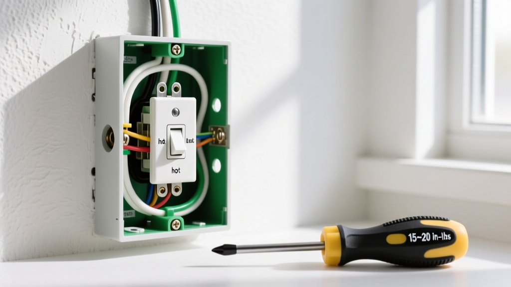
Remove the top and bottom mounting screws. Gently pull the switch out of the gang box. Do not touch any bare wires yet. Take a photo of the existing wiring. In a standard single pole setup, you will see two insulated wires (usually black, or one black and one white with black tape) connected to the two brass terminal screws, and a bare copper or green wire connected to the green grounding screw.
Step 3: Prep the Wire Ends
Disconnect the wires. Inspect the copper ends. If they are scored, bent, or blackened from previous arcing, snip them back and re-strip exactly 3/4 inch of insulation. Exposed copper beyond the terminal washer is a severe shock hazard and a common failure mode flagged during home inspections.
Step 4: Form the J-Hook and Connect
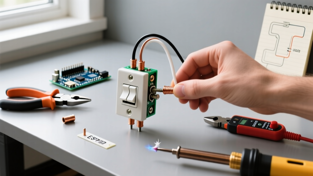
Using needle-nose pliers, bend the bare copper into a tight "J" hook. Critical Rule: The open end of the hook must face clockwise. When you tighten the terminal screw (which turns clockwise), the screw head will pull the hook tighter around the shaft. If hooked counter-clockwise, the screw will push the wire out, leading to a loose connection, arcing, and potential fire.
Step 5: Secure the Ground
Attach the bare copper ground wire to the green grounding screw on the switch strap. If the metal gang box is present, NEC code requires the box itself to be grounded, often achieved via a pigtail wire connecting the box to the main ground bundle.
Wire Identification and Troubleshooting Matrix
Beginners often confuse wire functions. Use this matrix to identify what you are looking at inside the gang box.
| Wire Color | Standard Function | Switch Terminal | Edge Case / Warning |
|---|---|---|---|
| Black | Hot (Line or Load) | Brass Screw | On a single pole, line/load orientation doesn't matter. Either brass screw works. |
| White (with black tape) | Switch Leg (Hot) | Brass Screw | White wire used as a hot must be marked with black tape or marker per NEC 200.6(E). |
| White (untaped) | Neutral | None (Bypass) | Neutrals bypass standard switches and connect directly to the light fixture. |
| Bare / Green | Equipment Ground | Green Screw | Must be securely fastened; prevents shock if a hot wire touches the metal strap. |
Modern Code Considerations: Smart Switches and Neutrals
If your goal is to install a smart switch (like a Lutron Caseta or Kasa Smart) instead of a mechanical toggle, your wiring requirements change. Smart switches contain internal circuit boards that require constant standby power. This means they need a neutral wire (the bundle of white wires pushed to the back of the box) to complete their internal circuit.
If you open your gang box and only see two black wires and a ground (a "switch loop" with no neutral), you cannot install a standard Wi-Fi or Z-Wave smart switch. You must either pull new 14/3 or 12/3 Romex cable from the fixture, or opt for a specialized "no-neutral" switch like the Lutron Caseta (Model PD-6ANS), which utilizes a bypass capacitor installed at the light fixture to trickle current.
Common Beginner Failure Modes
The "Backstab" Mistake: Many budget switches feature push-in "backstab" holes on the rear. The Consumer Product Safety Commission (CPSC) and master electricians universally advise against using these. The internal spring clips loosen over time due to thermal expansion and contraction, leading to high-resistance connections, melted plastic, and fires. Always use the side terminal screws with your J-hook method.
Box Fill Violations
Cramming stiff 12 AWG wire, a deep smart switch, and wire nuts into a shallow 18-cubic-inch box violates NEC Article 314. If the wires are aggressively bent and pressing hard against the back of the switch, you risk shorting a hot wire against the metal box or damaging the insulation. If the box is too full, replace it with a deeper "old work" box or use a switch with a shallower chassis.
Frequently Asked Questions
Does it matter which brass screw gets the hot wire?
On a standard, single pole mechanical switch, no. The switch simply acts as a drawbridge. Current flows across the bridge regardless of which side it enters. However, if you are installing a smart switch, dimmer, or timer, the manufacturer will explicitly label one screw as "LINE" (power from panel) and the other as "LOAD" (power to the light). Reversing these on electronic switches will prevent them from turning on or cause internal component failure.
Why is my switch warm to the touch?
A standard 15A switch controlling a few LED bulbs should be room temperature. If it is warm, you may have a loose terminal connection causing electrical resistance (which generates heat), or you are exceeding the switch's amperage rating. For heavy loads like baseboard heaters or large shop vacuums, you must upgrade to a 20A switch and ensure the circuit wiring is 12 AWG.
Final Testing and Reassembly
Once all wires are secured, gently fold them into the back of the box in a Z-pattern. Mount the switch using the provided screws, ensuring the strap sits flush against the drywall or plaster. If the switch is crooked, loosen the screws, adjust the strap within the mounting slots, and retighten. Attach the wall plate, restore power at the breaker, and test the fixture. By following these precise electrical switch wiring protocols, you ensure a safe, code-compliant, and lasting installation.