
The Definitive Wiring Diagram Reference for Electric Outlet Installation
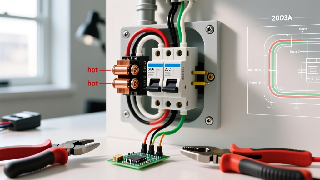
Performing a safe and code-compliant electric outlet installation requires more than just matching wire colors to screw terminals. As electrical systems evolve, so do the National Electrical Code (NEC) requirements and manufacturer specifications. In 2026, the integration of tamper-resistant (TR) mechanisms, advanced ground-fault circuit interrupter (GFCI) diagnostics, and strict torque requirements mean that even veteran DIYers must reference updated wiring schematics. This comprehensive guide serves as your master wiring diagram reference for standard duplex, GFCI, and split-wired receptacles, complete with exact installation specifications.
Core Anatomy and Terminal Mapping Matrix
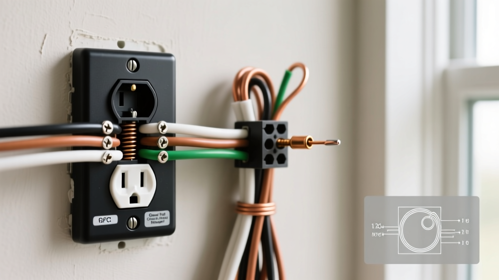
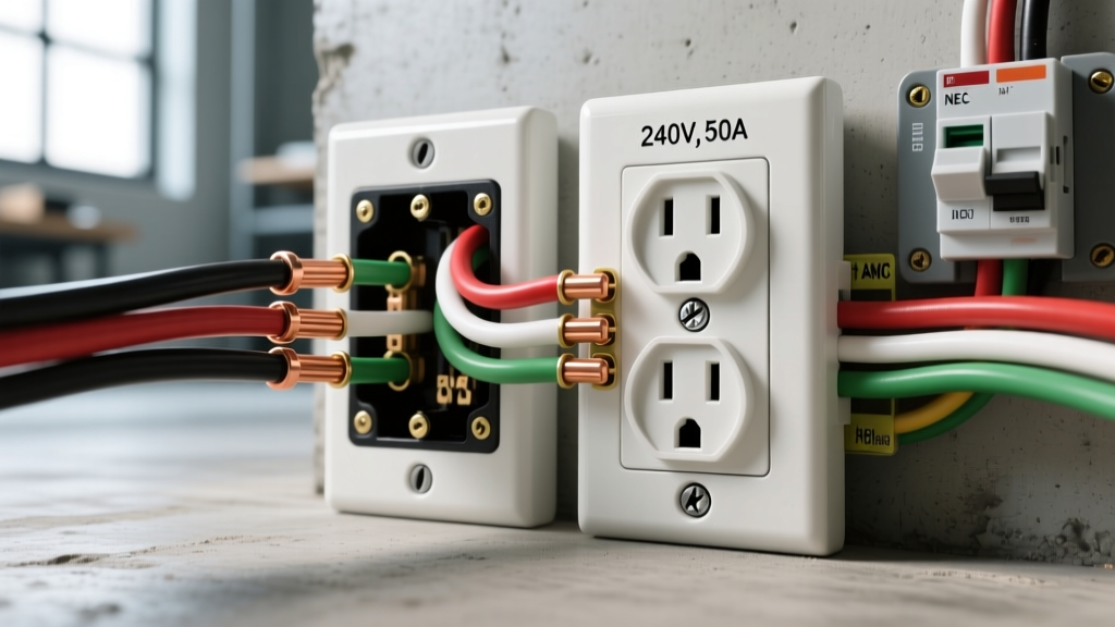
Before executing any electric outlet installation, you must understand the physical anatomy of a standard NEMA 5-15R or 5-20R receptacle. Modern receptacles feature three primary connection zones: the brass (hot) terminals, the silver (neutral) terminals, and the green (ground) screw. While older installations relied heavily on push-in backstab connections, the National Fire Protection Association (NFPA) and modern best practices strongly mandate the use of side-wiring or screw-and-clamp back-wiring to prevent arcing and thermal failure over time.
| Wire Insulation Color | Terminal Screw Color | Electrical Function | NEC Article Reference |
|---|---|---|---|
| Black (or Red/Blue) | Brass (Gold) | Ungrounded Conductor (Hot) | NEC 200.10(C) |
| White (or Gray) | Silver | Grounded Conductor (Neutral) | NEC 200.10(B) |
| Bare Copper (or Green) | Green | Equipment Grounding Conductor | NEC 250.146 |
Diagram Reference 1: Standard 15A/20A Duplex Receptacles
Scenario A: End-of-Run (Last Outlet on the Circuit)
When the receptacle is the final device on the branch circuit, you will only have one set of incoming wires (1x Hot, 1x Neutral, 1x Ground). Connect the black wire to the brass screw, the white wire to the silver screw, and the bare copper to the green ground screw. For a 15-amp circuit (14 AWG wire), a standard Leviton T5262-HGY ($2.50 - $4.00) is ideal. For a 20-amp circuit (12 AWG wire), use a Hubbell 5262-SW ($3.00 - $5.50) which features a T-slot neutral to accept both 15A and 20A plugs.
Scenario B: Middle-of-Run (Daisy-Chaining)
When feeding power downstream to another outlet, you will have two sets of wires (incoming and outgoing). Never use the push-in backstab holes to connect two wires. Instead, use the screw-and-clamp plates found on commercial-grade receptacles, which allow you to insert two stripped wires straight back and tighten the screw to clamp them securely. Alternatively, create a pigtail using a wire nut or a WAGO 221 lever connector to join the incoming and outgoing wires, then run a single jumper wire to the receptacle terminal.
Pro-Tip for Pigtailing: Always use a 6-inch length of solid copper wire matching the circuit gauge (14 AWG for 15A, 12 AWG for 20A) for pigtails. This ensures the grounding path remains intact even if the receptacle is removed for future servicing, satisfying NEC 250.148.
Diagram Reference 2: GFCI Receptacle (Line vs. Load)
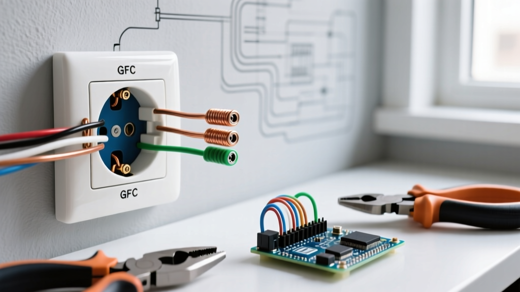
GFCI receptacles, such as the Eaton GFNT2-W ($16.00 - $22.00), are mandatory in wet locations per the U.S. Consumer Product Safety Commission (CPSC) guidelines and NEC Article 210.8. The most common failure in electric outlet installation involving GFCIs is confusing the LINE and LOAD terminals.
- LINE Terminals (Power In): Connect the incoming hot and neutral wires from the breaker panel here. These terminals power the GFCI's internal circuitry and the receptacle face.
- LOAD Terminals (Power Out): Connect downstream hot and neutral wires here ONLY if you intend to provide GFCI protection to subsequent outlets on the same circuit.
Critical Edge Case: If you are installing a GFCI at the end of a run, or if local code requires individual GFCI protection per receptacle (common in commercial kitchens), do not use the LOAD terminals. Leave them empty and ensure the yellow warning tape covering them remains intact. Connecting incoming power to the LOAD terminals will result in a dead receptacle that will not reset.
Diagram Reference 3: Split-Wired (Half-Hot) Receptacles
Split-wired receptacles are frequently used in living rooms and bedrooms where one half of the duplex outlet is controlled by a wall switch (for lamps) and the other half remains always-on. This requires a 3-wire cable (e.g., 14/3 or 12/3 Romex) containing a black (always hot), red (switched hot), white (shared neutral), and bare (ground) wire.
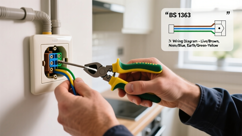
- Break the Brass Fin: Use needle-nose pliers to snap off the small brass connecting tab on the hot side of the receptacle. Do not break the silver fin on the neutral side.
- Connect the Hots: Attach the black wire to the top brass screw and the red wire to the bottom brass screw.
- Connect Neutral and Ground: Attach the white wire to either silver screw and the bare wire to the green screw.
Multi-Wire Branch Circuit (MWBC) Warning: If the black and red wires are on different phases of a shared neutral MWBC, NEC Article 210.4(B) mandates that the two breakers must be tied together with an approved handle tie or a double-pole breaker to ensure simultaneous disconnection, preventing lethal neutral overloads.
Critical Installation Specifications & Torque Values
Under NEC 110.14(D), electrical connections must be torqued to the manufacturer's specified values. Loose connections cause high resistance, leading to thermal expansion, arcing, and eventual fires. The Occupational Safety and Health Administration (OSHA) frequently cites improper termination torque in industrial and commercial inspections, but this standard equally applies to residential safety.
| Specification Metric | 14 AWG (15A Circuit) | 12 AWG (20A Circuit) |
|---|---|---|
| Terminal Torque (Side Wire) | 12 - 14 in-lbs | 12 - 14 in-lbs |
| Terminal Torque (Screw-and-Clamp) | 14 - 16 in-lbs | 14 - 16 in-lbs |
| Wire Strip Length (Side Wire) | 5/8 inch | 5/8 inch |
| Wire Strip Length (Back-Clamp) | 3/4 inch | 3/4 inch |
Tool Recommendation: Do not guess the tightness by hand. Use a calibrated torque screwdriver, such as the Klein Tools 60004, set to 14 in-lbs for standard Leviton and Hubbell commercial receptacles.
Troubleshooting Common Wiring Failures
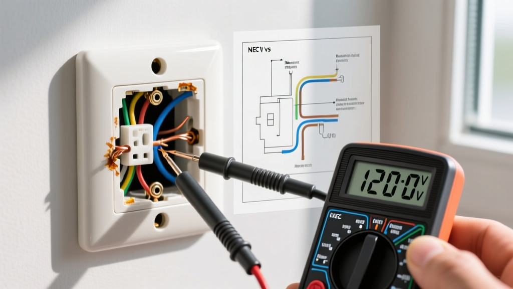
After completing your electric outlet installation, verify the wiring using a digital receptacle tester like the Klein Tools RT250 or a Fluke T6-1000. Below are the most frequent failure modes and their diagram-based solutions:
- Reversed Polarity (Hot/Neutral Swapped): The tester shows an open hot or reversed wiring. Fix: Verify that the black wire is on the shorter slot (brass screw) and the white wire is on the wider slot (silver screw).
- Open Ground: The ground path is broken. Fix: Check the green screw. If the metal box is grounded but the receptacle lacks a ground wire, ensure the receptacle yoke makes firm, unpainted contact with the metal box, or install a GFCI and label it "No Equipment Ground" per NEC 406.4(D).
- GFCI Trips Immediately Upon Reset: Fix: This usually indicates a shared neutral downstream or a ground fault in a connected appliance. Disconnect the LOAD wires. If the GFCI holds, the fault lies in the downstream wiring. Check for pinched wires or a neutral-to-ground short in a downstream junction box.
- Breaker Trips Instantly on Split-Wired Outlet: Fix: You likely failed to break the brass fin, creating a direct dead short between the two hot legs (black and red). Turn off power, remove the receptacle, and ensure the brass tab is completely severed.
Final Thoughts on Code Compliance
A successful electric outlet installation bridges the gap between theoretical diagrams and physical execution. Always ensure your wire gauge matches the breaker size (14 AWG for 15A, 12 AWG for 20A), utilize screw-and-clamp terminations over backstabs, and adhere strictly to manufacturer torque specifications. By referencing these specific wiring topologies, you ensure a resilient, fire-resistant, and code-compliant electrical system that will perform safely for decades.