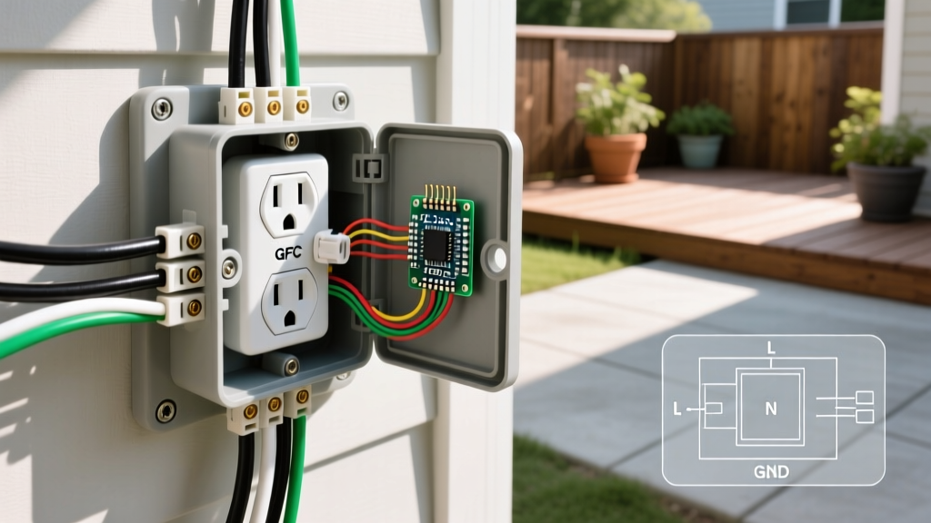

The Critical Importance of Code-Compliant Outdoor Power
Adding exterior power transforms how you use your outdoor space, enabling everything from electric vehicle charging and landscape lighting to heavy-duty power tools. However, installing an outdoor electrical outlet introduces severe environmental variables—moisture, UV degradation, and temperature fluctuations—that demand strict adherence to the National Electrical Code (NEC). According to the U.S. Consumer Product Safety Commission (CPSC), ground-fault incidents in damp locations remain a leading cause of residential electrical shocks, making proper GFCI integration and weatherproof sealing non-negotiable.
This guide bypasses generic advice to provide a master-level, step-by-step installation protocol. We will cover exact material specifications, NEC burial depth requirements, and precise torque settings to ensure your installation is safe, durable, and inspection-ready.
⚠️ SAFETY DIRECTIVE: Never work on live circuits. Always shut off the breaker, apply a lockout/tagout (LOTO) device, and verify zero voltage with a calibrated tester before touching any conductor. If your home lacks an equipment grounding conductor (EGC), consult a licensed electrician to upgrade the circuit.
NEC 2023/2026 Requirements for Exterior Receptacles
Before purchasing materials, you must understand the current code landscape governing outdoor receptacles. The National Fire Protection Association (NFPA 70 / NEC) mandates specific protections for exterior circuits:
- GFCI Protection (NEC 210.8(F)): All 125V to 250V, 15A and 20A receptacles installed outdoors must have Ground-Fault Circuit Interrupter (GFCI) protection. There are no exceptions for dedicated circuits.
- Weatherproof Covers (NEC 406.9(B)(1)): An "extra-duty" or "in-use" weatherproof cover is required. The cover must remain closed and sealed even when a cord is plugged into the receptacle.
- Damp/Wet Location Ratings: All boxes, fittings, and conduit bodies must be explicitly listed for wet locations.
Master Materials & Tools Matrix
Cheap materials fail prematurely when exposed to the elements. Below is the recommended bill of materials (BOM) for a premium, long-lasting installation.
| Component | Recommended Model / Spec | Est. Cost | Why It Matters |
|---|---|---|---|
| GFCI Receptacle | Leviton GFNT2-W (20A, Self-Test) | $24.00 | Features auto-monitoring that cuts power if GFCI protection is compromised. |
| Weatherproof Box | Arlington 8100 Non-Metallic (3-Gang) | $16.50 | Deep profile accommodates bulky GFCI bodies and 12 AWG wire folds. |
| In-Use Cover | TayMac MM410W Extra-Duty Die-Cast | $19.00 | Heavy-duty aluminum resists UV warping and physical impacts. |
| Conductor | Southwire 12 AWG THWN-2 (in conduit) | $0.65/ft | Superior to UF-B for conduit runs; resists soil pH degradation. |
| Sealant | GE Advanced Silicone 2 (Clear) | $8.50 | Remains flexible in sub-zero temperatures; won't crack like acrylic caulk. |
Required Tooling: Klein Tools NCVT-3 Non-Contact Voltage Tester, Klein 11055 Wire Strippers, Wiha Insulated Torque Screwdriver (calibrated to 14 in-lbs), and a trenching shovel or vibratory plow.
Phase 1: Trenching and Conduit Routing
How you route power from your main panel or interior sub-panel to the exterior wall dictates the longevity of the circuit. While direct-burial UF-B cable is permitted, running individual THWN-2 conductors inside Schedule 40 PVC conduit is the professional standard. Conduit provides physical protection against shovel strikes and allows you to pull new wires if a short occurs, without digging up your yard.
NEC Table 300.5: Minimum Burial Depths
| Wiring Method | Residential Branch Circuits (120V-240V, Max 20A) | Required Fittings |
|---|---|---|
| Direct Burial UF-B Cable | 12 Inches | Must transition to conduit 12" below grade to 8' above grade. |
| THWN-2 in PVC Conduit | 18 Inches | Water-tight sweep elbows, PVC solvent cement. |
| Rigid Metal Conduit (RMC) | 6 Inches | Threaded couplings, grounding bushings. |
Pro-Tip: Lay a continuous strip of bright red "Caution: Buried Electric Line" warning tape exactly 12 inches above your conduit before backfilling. This provides a critical visual warning for anyone digging in the future.
Phase 2: Step-by-Step Installation Protocol
Step 1: Mounting the Weatherproof Box
Position the Arlington 8100 box on the exterior siding. Use a torpedo level to ensure it is perfectly plumb. Drill pilot holes through the mounting flanges. Before driving the exterior-grade stainless steel screws, apply a thick bead of GE Advanced Silicone 2 to the back of the box flange. This prevents capillary action from drawing wind-driven rain behind your siding. Secure the box and wipe away excess silicone immediately.
Step 2: Pulling the Conductors
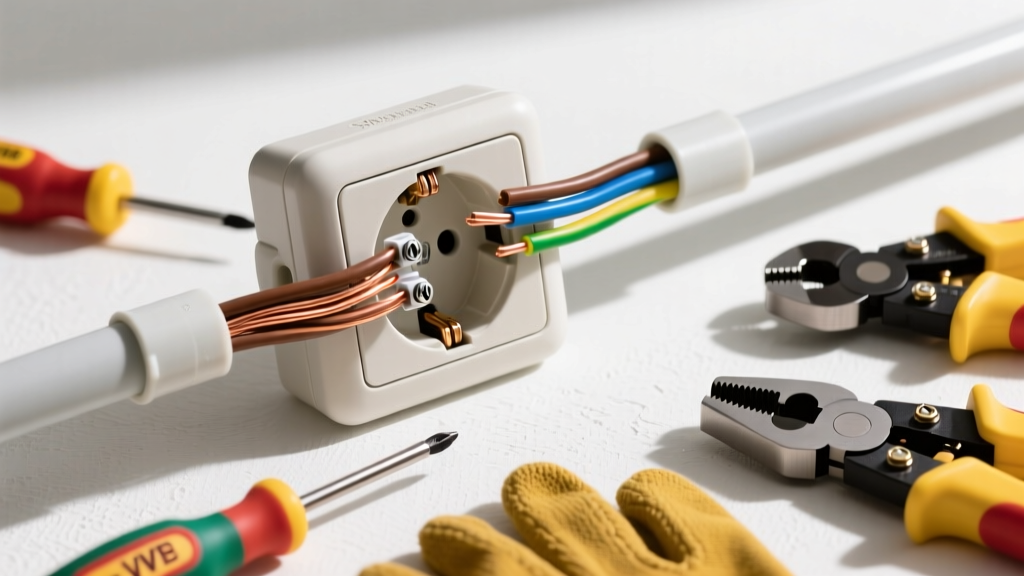
Feed your red (hot), white (neutral), and green/bare (equipment ground) THWN-2 wires through the PVC conduit and into the weatherproof box. You must leave at least 6 inches of free conductor length extending past the front edge of the box (NEC 300.14). Strip exactly 3/4 inch of insulation from the ends of the red and white wires using your Klein 11055 strippers. Do not nick the copper, as scoring the metal creates a high-resistance hot spot that can melt the terminal over time.
Step 3: Terminating the GFCI Receptacle
This is where most DIY failures occur. A GFCI receptacle has two distinct sets of terminals: LINE and LOAD.
- LINE Terminals: Connect the incoming power from the breaker panel here. The black/red wire goes to the brass LINE screw; the white wire goes to the silver LINE screw.
- LOAD Terminals: ONLY use these if you are extending GFCI protection to a downstream receptacle. If this is the only outlet on the circuit, leave the LOAD terminals completely empty and cover them with the included yellow warning tape.
Wrap the bare copper ground wire around the green grounding screw on the bottom of the yoke. Additionally, if you are using a metal weatherproof box, you must run a 12 AWG copper pigtail from the ground screw to a grounding clip or 10-32 ground screw tapped into the back of the metal box.
Step 4: Applying Precise Torque
The NEC now mandates that terminals be tightened to the manufacturer's specified torque. Under-tightened screws cause arcing and fires; over-tightened screws strip the brass threads. Set your Wiha insulated torque screwdriver to 14 in-lbs (the standard spec for Leviton 15A/20A receptacles). Tighten each terminal screw until the driver clicks. Verify that no bare copper is exposed outside the terminal saddle, and that no insulation is trapped beneath it.
Step 5: Sealing and Final Assembly
Carefully fold the wires into the box using a "figure-8" or accordion fold to avoid pinching the insulation against the sharp edges of the conduit hub. Mount the Leviton GFCI to the box using the provided 6-32 machine screws. Place the foam gasket over the receptacle, then mount the TayMac MM410W in-use cover. Secure the cover with its mounting screws and apply a final bead of silicone across the top and side seams of the cover hood—never seal the bottom edge, as this traps condensation inside the cover.
Testing and Edge-Case Troubleshooting
Once the breaker is restored, the GFCI's green LED should illuminate, indicating proper wiring and power. Press the "TEST" button on the receptacle face; the red "RESET" button should pop out, and the LED should turn off. Press "RESET" to restore power. Verify functionality using a receptacle tester (e.g., Klein Tools RT212).
Common Failure Modes & Solutions
- Nuisance Tripping During Rainstorms: This usually indicates a failed gasket seal or a conduit fitting that was not glued with PVC solvent cement, allowing groundwater to wick into the box. Disassemble, dry with compressed air, and re-seal using marine-grade duct seal compound around the conduit entry hub.
- Breaker Trips Immediately Upon Reset: You have likely wired the LINE and LOAD terminals backward, or a downstream neutral is sharing a path with another circuit. Verify incoming voltage is strictly on the LINE terminals.
- Voltage Drop on Long Runs: If your trench is over 75 feet long, standard 12 AWG wire will experience a voltage drop exceeding the recommended 3% limit under heavy load (e.g., running a 15A table saw). Upsize your conductors to 10 AWG THWN-2 to compensate for the distance.
Frequently Asked Questions (FAQ)
Can I install an outdoor outlet without a ground wire?
If you are replacing an existing ungrounded receptacle on an older home, the NEC allows you to install a GFCI receptacle and label it "No Equipment Ground" and "GFCI Protected." However, for a new circuit installation in 2026, an equipment grounding conductor (EGC) is absolutely mandatory. You cannot run a new ungrounded circuit.
Do I need a dedicated circuit for my outdoor outlet?
Not necessarily. You can tap into an existing indoor 20A small-appliance branch circuit, provided the total load does not exceed 80% of the breaker's capacity (16A continuous). However, if you plan to use high-draw equipment like EV chargers, pressure washers, or commercial holiday lighting displays, pulling a dedicated 20A circuit from the panel is highly recommended to prevent nuisance breaker trips.
For further reading on workplace and residential electrical safety standards, refer to the Occupational Safety and Health Administration (OSHA) Electrical Safety guidelines. By prioritizing premium materials, precise torque, and rigorous weatherproofing, your outdoor electrical outlet will provide safe, reliable power for decades.