
Why Upgrade Your Electricity Outlet?
The standard electricity outlet (technically known as a duplex receptacle) is the most frequently used electrical component in any home. Yet, it is often ignored until a failure occurs. As of 2026, the proliferation of high-draw USB-C PD (Power Delivery) devices, combined with stricter National Electrical Code (NEC) safety mandates, makes upgrading aging receptacles a critical home maintenance task. Replacing a worn-out standard outlet with a modern Ground Fault Circuit Interrupter (GFCI) or a built-in USB-C receptacle not only brings your home up to current safety standards but also eliminates the need for bulky, heat-generating charging bricks.
Critical Warning Signs of a Failing Receptacle
Before deciding on an upgrade path, inspect your existing electricity outlets for these specific failure modes:
- Thermal Degradation: Discoloration or a melted appearance around the plug slots indicates internal arcing and extreme heat. This requires immediate replacement.
- Loss of Contact Tension: If a plug slides into the socket with zero resistance or falls out under the weight of its own cord, the internal brass wipers have lost their spring tension. This creates high-resistance connections that can start fires.
- Ungrounded (2-Prong) Configuration: Homes built before 1962 often lack an equipment grounding conductor. Leaving these in place violates modern safety expectations for surge protection.
- Cracked Faceplates or Yokes: Physical damage to the thermoplastic housing compromises the dielectric insulation barrier.
Choosing the Right Replacement Receptacle
When performing an electricity outlet replacement, you are not limited to a like-for-like swap. The table below compares the three most common upgrade paths available in 2026, including specific model recommendations and average retail pricing.
| Receptacle Type | Recommended Model (2026) | Best Application | Avg. Cost | Key Technical Spec |
|---|---|---|---|---|
| Standard Tamper-Resistant (TR) | Leviton T5320-W | Living rooms, bedrooms (general use) | $3.50 - $5.00 | 15A / 125V, TR shutters |
| GFCI (Ground Fault) | Eaton GFTR15W | Kitchens, bathrooms, garages, outdoors | $20.00 - $28.00 | Trips at 4-6mA leakage |
| USB-C / USB-A Integrated | Leviton T5636 (USB-C PD) | Kitchen islands, nightstands, home offices | $35.00 - $45.00 | 30W USB-C PD 3.1 output |
Required Tools for a Code-Compliant Installation
Professional electricians do not rely on guesswork. To ensure your electricity outlet upgrade is safe and passes inspection, gather the following tools:
- Non-Contact Voltage Tester: Klein Tools NCVT-3 (Dual-range AC/DC) to verify the circuit is de-energized.
- Receptacle Tension Tester: To verify the grip of the new outlet post-installation.
- Wire Strippers: Klein Tools 11063W (for 14-10 AWG) to ensure precise insulation removal without nicking the copper conductor.
- Torque Screwdriver: Klein Tools 32500TORQ. Expert Note: The 2023 and 2026 NEC cycles strictly mandate that terminal screws be tightened to the manufacturer's specified torque (typically 14 in-lbs for standard 15A receptacles) to prevent thermal loosening over time.
Step-by-Step Electricity Outlet Replacement Procedure
Step 1: Isolate and Verify the Circuit
Turn off the corresponding breaker at the main panel. Insert your NCVT-3 into both the top and bottom slots of the existing electricity outlet. Test the tester on a known live circuit immediately afterward to confirm the tool's battery and sensor are functioning correctly.
Step 2: Extract and Map the Wiring
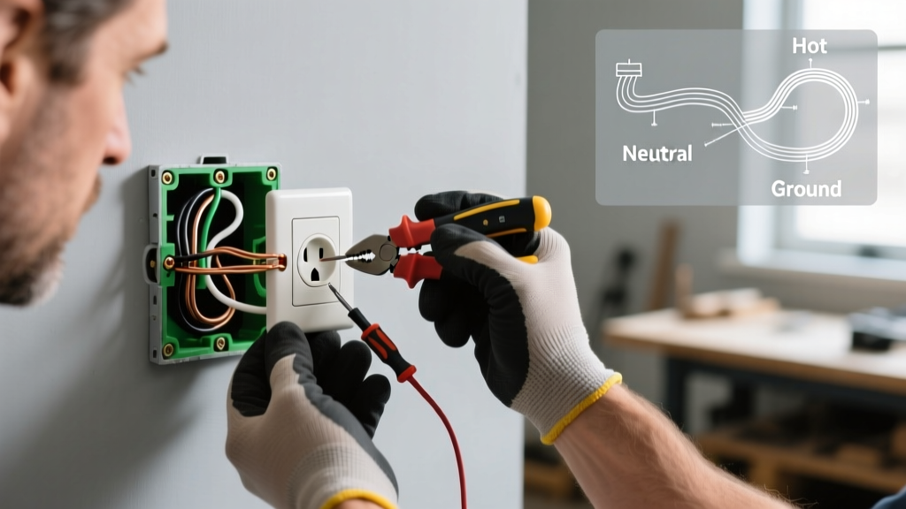
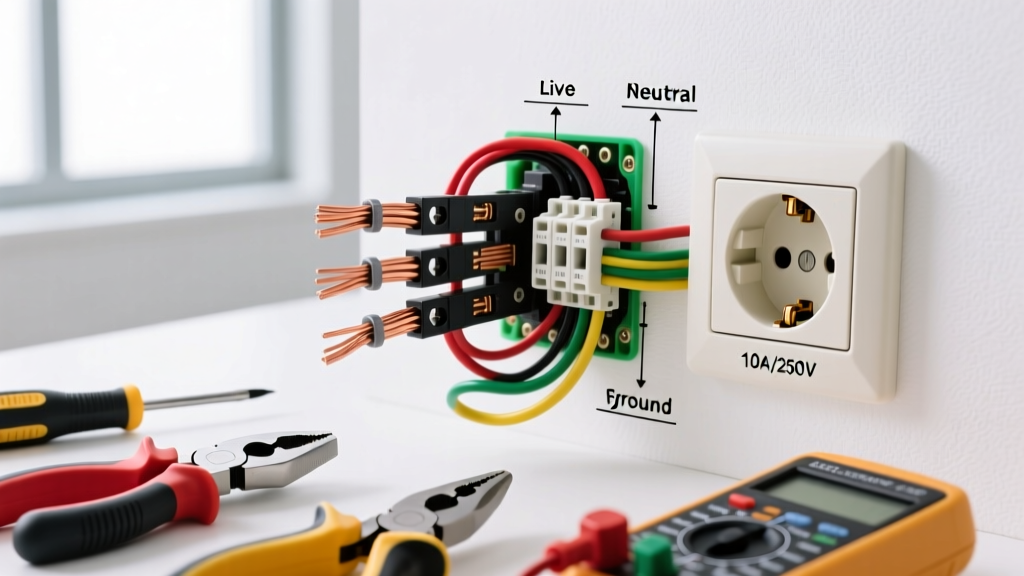
Remove the faceplate and the two mounting screws. Gently pull the receptacle out of the gang box. Do not disconnect any wires yet. Take a photo of the existing wiring. Identify the Line (power coming from the panel) and the Load (power continuing to downstream outlets). If only one black and one white wire are present, it is a simple end-of-run circuit.
Step 3: Prepare the Conductors
If reusing existing wires, use your wire strippers to clean off any old oxidation or bent hooks. Strip exactly 3/4-inch of insulation for 14 AWG wire, or up to 1-inch for 12 AWG wire, depending on the strip gauge marked on the back of your new receptacle. A proper strip length ensures no bare copper is exposed outside the terminal, and no insulation is trapped under the screw head.
Step 4: Terminate and Torque
Form a clockwise shepherd's hook with the wire so that tightening the screw pulls the loop closed rather than pushing it out. Place the wire under the terminal screw. Using your calibrated torque screwdriver, tighten the screw until it clicks at the manufacturer's specified rating (usually 14 in-lbs). For GFCI or USB receptacles, consider using the back-wire push-in clamps (not the cheap stab-in connectors found on $1 outlets) as they provide a larger surface area contact and are less prone to loosening under thermal cycling.
Step 5: Fold and Mount
Carefully fold the wires back into the gang box using a Z-fold pattern. Push the receptacle flush against the drywall or plaster. Use the provided mounting screws, ensuring the yoke does not bend. A bent yoke can cause the internal grounding strap to short against a metal gang box.
Navigating NEC Codes for Older Homes
One of the most common scenarios in residential retrofits is replacing an ungrounded (2-prong) electricity outlet. According to the National Fire Protection Association (NFPA) and the National Electrical Code (NEC) Section 406.4(D), you cannot simply swap a 2-prong outlet for a standard 3-prong outlet without running a new equipment grounding conductor back to the panel.
NEC 406.4(D)(2) Exception: Where no equipment grounding conductor exists, replacement is permitted with a GFCI-type receptacle. The receptacle must be marked with a "GFCI Protected" and "No Equipment Ground" label, which are typically included in the product packaging.
This upgrade provides life-saving ground fault protection (tripping at 5 milliamps of leakage) even without a physical ground wire, satisfying modern safety requirements while protecting sensitive electronics from minor surges. For comprehensive safety guidelines on ground fault protection, refer to the Consumer Product Safety Commission (CPSC) GFCI documentation.
Advanced Troubleshooting & Edge Cases
The Multi-Wire Branch Circuit (MWBC) Trap
If you open the gang box and find two black wires, two white wires, and a single red wire, you are likely dealing with a Multi-Wire Branch Circuit. This means the top and bottom halves of the electricity outlet are on two different breakers sharing a single neutral wire.
Action Required: You must break the brass hot-side tab on the new receptacle to keep the circuits separated. Furthermore, the two breakers in the panel must be tied together with a handle tie or be a single double-pole breaker to ensure simultaneous disconnection, preventing a deadly backfeed through the shared neutral.
GFCI Tripping Immediately Upon Reset
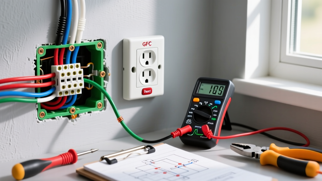
If your newly installed GFCI electricity outlet refuses to stay reset, check for the following:
- Reversed Line/Load: The most common error. Power must enter the terminals marked "LINE". If connected to "LOAD", the GFCI will either not reset or will fail to protect downstream devices.
- Downstream Neutral Sharing: If the downstream outlets share a neutral wire with a circuit not protected by the GFCI, the imbalance will cause an immediate trip. You must isolate the neutrals in the downstream boxes.
- Moisture in Outdoor Boxes: Ensure the weatherproof bubble cover is fully sealed and that no water has infiltrated the gang box, which will cause continuous micro-leakage to ground.
Final Inspection and Testing
Once the faceplate is secured and power is restored at the panel, use a standard 3-light receptacle tester to verify correct wiring (two amber lights indicate correct polarity and grounding). If you installed a GFCI, press the "TEST" button on the receptacle itself to ensure the internal solenoid physically trips the mechanism. Finally, plug in a high-draw device (like a hair dryer or space heater) for 5 minutes, then use an infrared thermometer to check the terminal area; a temperature rise of more than 15°F above ambient indicates a poor connection requiring re-torquing.