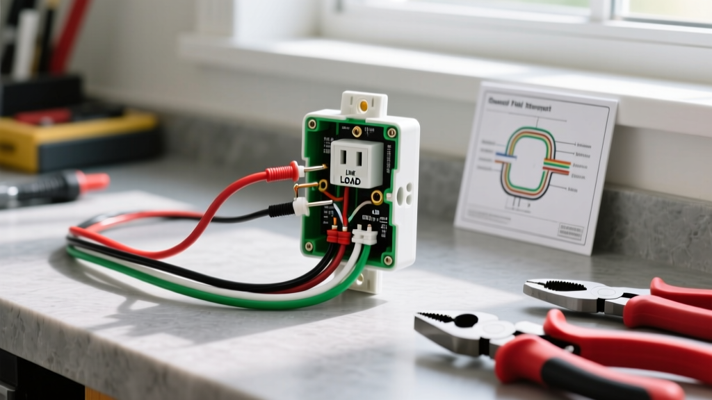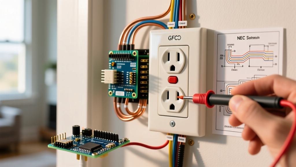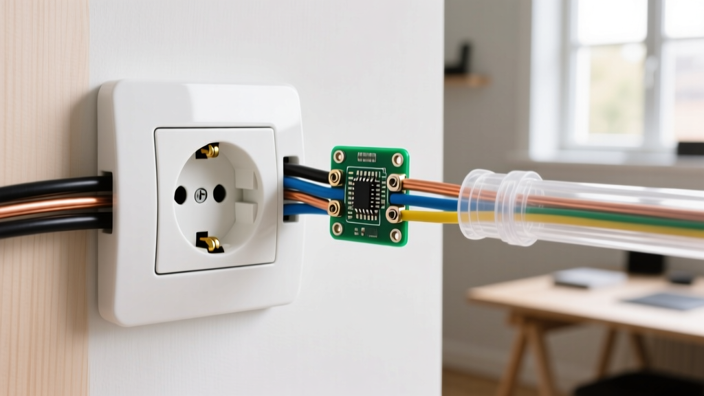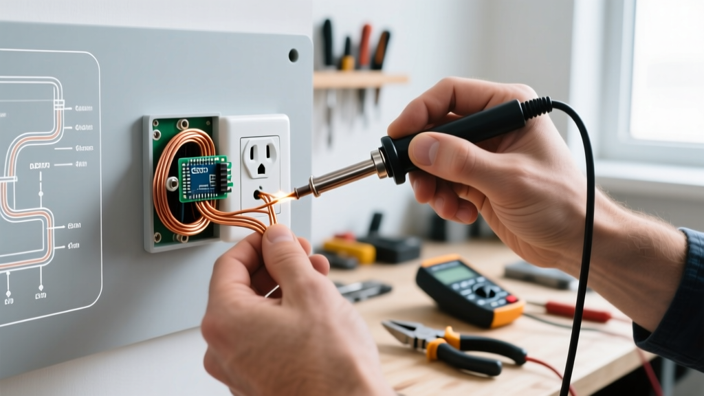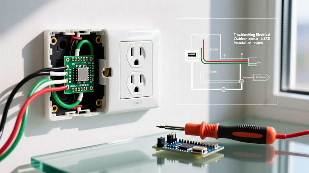

Upgrading to a USB-integrated receptacle is one of the most popular modern home electrical projects. However, when troubleshooting an electrical outlet with USB installation, electricians and DIYers frequently encounter issues that standard duplex receptacles simply do not present. Unlike a simple brass-and-copper pass-through device, a USB receptacle contains an internal switching power supply that steps 120V AC down to 5V DC (or higher for USB-C Power Delivery). This internal circuitry introduces thermal constraints, strict box-fill requirements, and complex failure modes.
If your newly installed USB outlet is tripping breakers, failing to charge devices, or running dangerously hot, this guide will walk you through the exact diagnostic procedures required to identify and resolve the fault.
Diagnostic Matrix: Symptom to Root Cause
Before opening the junction box, match your specific symptoms to the likely electrical faults below. This matrix isolates the most common failure points in USB receptacle circuits.
| Observed Symptom | Primary Root Cause | Secondary Check |
|---|---|---|
| AC outlets work, USB ports are completely dead | Missing or disconnected Neutral wire | Check for misidentified switch loops |
| Breaker trips immediately upon plugging in a device | Ground fault or pinched internal transformer | Inspect box fill and wire crushing |
| USB charging is intermittent or extremely slow | Thermal throttling due to shallow box | Verify box cubic inch capacity |
| Faceplate is hot to the touch or melting | Over-torqued terminals or backstab failure | Check termination torque specs |
| USB-C PD negotiation fails (defaults to 5W) | Internal step-down logic board failure | Test with a known-good PD cable |
The #1 Installation Killer: Box Fill and Thermal Constraints
The most frequent cause of premature failure in a USB receptacle is ignoring National Fire Protection Association (NFPA) box fill calculations. Standard residential junction boxes are often 18 cubic inches (cu in). However, the internal switching power supply of a USB-C/A combo receptacle (like the Leviton T5636 or TopGreener TU2154C) is exceptionally bulky and generates significant ambient heat during the AC-to-DC conversion process.
Diagnosing Thermal Throttling
Modern USB receptacles feature internal thermistors. If the ambient temperature inside the junction box exceeds 60°C (140°F), the internal logic board will intentionally throttle the charging output to prevent a fire. If your outlet charges a phone at 25W when first plugged in, but drops to 5W after 10 minutes, you are experiencing thermal throttling.
- The Fix: You must upgrade to a deep junction box. For a single USB receptacle with two 14/2 NM cables, the U.S. Consumer Product Safety Commission (CPSC) and NEC guidelines dictate a minimum of 22 to 24 cubic inches to allow adequate heat dissipation.
- Warning Sign: If the polycarbonate faceplate feels hot to the touch, power down the circuit immediately. Continuous thermal stress will degrade the internal capacitors and cause catastrophic failure.
The Phantom Neutral: Switch Loops and Miswiring
A standard duplex receptacle requires a Line (Hot), a Neutral, and a Ground. The USB ports require the exact same 120V AC circuit to feed their internal transformer. The most catastrophic error during an electrical outlet with USB installation occurs when an installer mistakes a white wire in a switch loop for a neutral.
Expert Insight: In older homes (pre-2011 NEC), a white wire was frequently used as the 'Line' or 'Load' in a switch loop and was not required to be marked with black tape. If you connect the internal USB transformer's neutral pigtail to a switch-loop white wire, you are either feeding the transformer 120V without a return path (resulting in dead ports) or creating a dead short that will instantly destroy the internal step-down board.
How to Verify the Neutral
- Turn off the breaker and verify zero voltage with a non-contact tester.
- Pull the receptacle out and locate the bundle of white wires in the back of the box.
- Use a digital multimeter (DMM) set to AC Voltage. Turn the breaker back on.
- Measure between the black (Hot) wire and the white wire bundle. You must read a stable 120V (±5V). If you read 0V or a fluctuating ghost voltage, you do not have a true neutral in that box.
Termination Faults: Backstabbing vs. Torque Specifications
Never use the push-in backstab terminals on a USB receptacle. The internal transformer draws a continuous, albeit small, parasitic load even when no devices are plugged in, and the inrush current when a tablet is connected can cause micro-arcing inside weak backstab connections.
Proper Side-Wiring Protocol
You must use the side terminal screws. Furthermore, as of the 2026 NEC updates, torque verification is critical for devices with internal electronics. Over-torquing the brass terminal screws can strip the threads or warp the internal PCB mounting points, leading to hairline fractures in the solder joints connecting the AC terminals to the DC transformer.
- Wire Prep: Strip exactly 3/4 inch of insulation. Do not nick the copper conductor.
- Hook Direction: Form a clockwise J-hook so the wire pulls tighter as the screw is driven.
- Torque Spec: Use a calibrated inch-pound torque screwdriver set to 14 to 16 in-lbs (always verify the exact spec printed on the device yoke, typically 14 in-lbs for Leviton and 16 in-lbs for TopGreener).
Step-by-Step Multimeter Troubleshooting Flow
If the physical installation checks out, use this diagnostic flow to isolate component-level failures.
Step 1: The No-Load Voltage Test
With nothing plugged into the USB ports, use a DMM set to DC Voltage. Insert the probes into the USB-A port (positive on the outer pins, negative on the inner mesh/ground). You should read exactly 5.0V to 5.2V. If you read 0V, the internal transformer has failed or the internal thermal fuse has blown.
Step 2: The Load Voltage Drop Test
Plug in a USB load tester (available for under $15 online). Draw 2.0 Amps from the port. Watch the DMM. If the voltage drops below 4.75V under load, the internal voltage regulator is failing to maintain regulation, indicating a defective unit that must be replaced.
Step 3: USB-C Power Delivery (PD) Handshake Check
USB-C ports rely on a digital handshake via the CC (Configuration Channel) pins. If your USB-C port is stuck outputting 5V/1A instead of the advertised 25W or 30W, the issue is rarely the outlet itself. First, test with an E-Marked 100W USB-C cable. Standard 3A cables lack the E-Marker chip required to trigger the higher voltage tiers (9V or 12V) from the receptacle's internal PD controller.
Recommended Replacement Models for Faulty Installs
If your diagnostic tests confirm a blown internal transformer or degraded logic board, do not attempt to repair the internal PCB. Replace the unit with a current-generation model that features advanced thermal protection:
- Leviton T5636 (USB-C/A Combo): Features a 25W max output with an integrated thermal cutoff switch. Excellent for standard 22 cu in boxes.
- TopGreener TU2154C (USB-C PD): Delivers up to 30W via USB-C Power Delivery 3.0. Requires a deep 24 cu in box due to the larger heat sink on the internal DC-DC buck converter.
Frequently Asked Questions (FAQ)
Why does my GFCI/USB combo outlet trip when I plug in my laptop?
Laptop chargers and high-draw USB-C devices utilize switching power supplies that can create minor leakage currents. If your GFCI/USB combo is nearing the end of its lifespan, its internal ground-fault sensor may be overly sensitive. Ensure the GFCI is rated for at least 20A if it is on a 20A circuit, and verify that the neutral pigtail is connected to the correct 'Line Neutral' terminal, not the 'Load Neutral'.
Can I daisy-chain USB outlets on the same circuit?
Yes, but you must connect the downstream wires to the 'LOAD' terminals of the first receptacle. However, be aware that each USB receptacle adds internal heat to the wall cavity. Daisy-chaining more than two USB receptacles in a single continuous run can cause cumulative voltage drop and thermal buildup. Always use 12 AWG wire for long daisy-chained runs to minimize voltage drop.
Is it normal for the USB outlet to buzz quietly?
A very faint, high-frequency whine (coil whine) from the internal inductors is normal under heavy load. However, a loud 60Hz hum or a sharp buzzing sound indicates a loose neutral connection or arcing at the terminal screws. Turn off the breaker immediately and re-torque all connections.