
The Anatomy of a Pigtail Electrical Outlet Failure
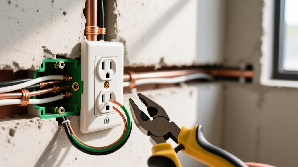
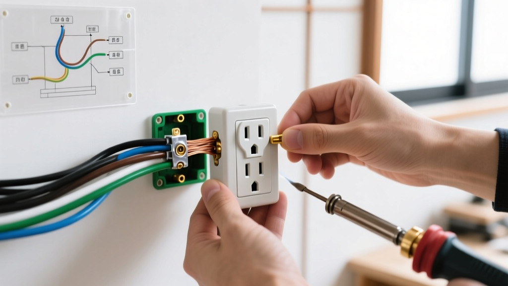
When a downstream receptacle suddenly loses power while the upstream device appears functional, the culprit is often a failed splice hidden inside the upstream junction box. In modern electrical wiring, a pigtail electrical outlet configuration involves using a short jumper wire (the 'pigtail') to connect the circuit's incoming line and outgoing load wires to a single terminal on the receptacle. While this method is vastly superior to daisy-chaining wires directly through the device's screw terminals, pigtails are not immune to failure. In 2026, with residential electrical loads increasing due to smart home hubs and high-draw appliances, thermal cycling at the splice point remains a primary cause of downstream power loss.
Step-by-Step Diagnostic Protocol
Troubleshooting a dead downstream circuit requires moving beyond simple non-contact voltage testers. You must verify voltage under load to identify high-resistance connections.
- Verify Panel Status: Ensure the 15A or 20A breaker has not tripped. Use a Klein Tools NCVT-41 at the panel to confirm the bus bar is energized.
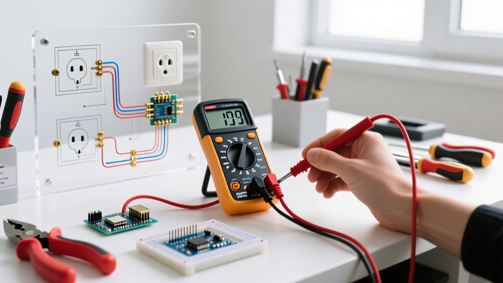
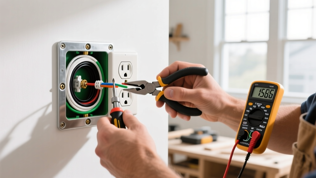
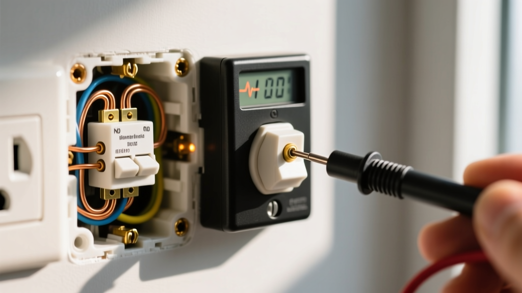
- Test the Downstream Receptacle: Insert a Fluke 117 True RMS Multimeter into the dead outlet. Test Hot-to-Neutral and Hot-to-Ground. If both read 0V, the upstream hot pigtail has failed. If Hot-to-Ground reads 120V but Hot-to-Neutral reads 0V, you have an open neutral.
- Isolate the Upstream Node: Turn off the breaker. Remove the upstream receptacle (the last known working outlet on the run).
- Inspect the Splice Mechanics: Look for discolored wire nuts, melted insulation, or copper strands that have sheared off during the twisting process.
Common Pigtail Failure Modes and Symptoms
| Failure Mode | Root Cause | Diagnostic Symptom |
|---|---|---|
| Thermal Creep | Repeated heating/cooling cycles loosen twist-on connectors over time. | Intermittent power loss when high-draw appliances (e.g., space heaters) cycle on. |
| Undersized Wire Nut | Using a yellow Ideal 33 on three 12 AWG wires exceeds the connector's spring capacity. | Wires pull out with minimal force; visible arcing marks inside the plastic skirt. |
| Sheared Conductor | Over-stripping and nicking the copper with wire strippers before pigtailing. | The pigtail snaps flush with the wire nut; downstream outlet is completely dead. |
| Backstabbed Upstream | The load wire was pushed into the backstab hole instead of being pigtailed to the screw. | Upstream outlet works, but downstream is dead; internal spring contact has fatigued. |
The Multi-Wire Branch Circuit (MWBC) Hazard
Advanced troubleshooters must consider the Multi-Wire Branch Circuit (MWBC) when diagnosing pigtail failures. An MWBC shares a single neutral wire between two hot legs (Phase A and Phase B) to return 120V current. If the neutral pigtail at the upstream outlet fails or is improperly daisy-chained through the receptacle yoke instead of being spliced, removing that outlet breaks the neutral path for the entire downstream circuit.
The Danger: Without a continuous neutral, the downstream 120V loads on Phase A and Phase B effectively become a series circuit across 240V. The device with the higher resistance will experience a massive voltage spike (often exceeding 180V), instantly destroying sensitive electronics like smart TVs or computer power supplies. According to the Consumer Product Safety Commission (CPSC), open neutrals are a leading cause of residential electrical fires and appliance destruction.
NEC 300.13(B) and the Neutral Continuity Rule
NEC 300.13(B) Device Removal: In multiwire branch circuits, the continuity of a grounded conductor shall not depend on device connections such as lampholders, receptacles, etc., where the removal of such devices would interrupt the continuity.
This code section mandates that neutrals must be pigtailed. While the National Electrical Code (NEC), maintained by the National Fire Protection Association (NFPA), technically allows hot wires to be daisy-chained through a standard receptacle's dual screw terminals, best practice in 2026 dictates pigtailing both the hot and the neutral. Pigtailing ensures that if the receptacle itself fails internally, the downstream circuit remains energized, drastically reducing troubleshooting time.
Upgrading Splices: Wago 221 vs. Twist-On Wire Nuts
When repairing a failed pigtail electrical outlet, the choice of connector dictates the longevity of the repair. Traditional twist-on wire nuts rely on installer torque and the internal steel spring to maintain contact pressure. Push-in lever connectors eliminate human error.
- Wago 221-413 (3-Port Lever Nut): Rated for 12-14 AWG solid and stranded wire. Provides a constant, spring-clamped connection pressure that resists thermal cycling. Cost: ~$0.45 per unit in 2026. Requires 11mm of stripped insulation.
- Ideal Twist-On 33 Yellow: The traditional standard for 3-wire splices. Cost: ~$0.08 per unit. Requires pre-twisting the wires for optimal contact on 12 AWG copper, though manufacturer instructions often state pre-twisting is optional (expert consensus strongly recommends pre-twisting to prevent internal arcing).
For troubleshooting and permanent repairs in tight junction boxes where a deep-set wire nut might snag on the grounding bundle, the compact profile of the Wago 221 series reduces box fill volume and prevents the pigtail from being crushed against the drywall when the receptacle is pushed back into the box.
Grounding Pigtails and Box Bonding Diagnostics
While hot and neutral failures cause immediate power loss, a failed grounding pigtail presents a silent, lethal hazard. In metal junction boxes, the equipment grounding conductor (EGC) must be bonded to the box itself, as well as pigtailed to the receptacle's green grounding screw. If a downstream outlet shows an 'Open Ground' on a standard three-prong receptacle tester, the fault often lies at the upstream metal box where the grounding pigtail has detached from the grounding clip or the green 10-32 grounding screw.
When troubleshooting an open ground on a metal box system, verify the continuity between the upstream box and the main panel's ground bus bar using your multimeter's continuity setting (ensure power is OFF). If the box is bonded but the downstream outlet lacks ground, the upstream grounding pigtail splice has likely failed due to corrosion or a loose wire nut. Upgrading to green, irreversible crimp rings for the box bond and using a dedicated Wago 221-413 for the grounding pigtail splice ensures a maintenance-free ground path that will survive decades of thermal expansion.
Expert Troubleshooting FAQ
Why does my downstream outlet read 40V to 80V instead of 0V or 120V?
This is a classic symptom of 'phantom voltage' or a high-resistance neutral connection. The digital multimeter's high impedance is picking up capacitive coupling from adjacent live wires. To confirm, plug in a solenoid voltage tester or a 15W incandescent test light. If the light does not illuminate, the circuit is open, and the upstream pigtail neutral splice has failed.
Can I use a crimp sleeve instead of a wire nut for pigtailing?
While copper crimp sleeves (like the King Innovation Copper Crimp) are UL-listed and provide a permanent, vibration-proof connection, they require a specialized crimping tool and cannot be easily undone for future diagnostics. For standard residential 15A and 20A receptacle pigtails, lever nuts or high-quality twist-on connectors remain the most practical and code-compliant choice.
What is the required pigtail length inside a standard single-gang box?
The NEC requires at least 6 inches of free conductor length measured from the point in the box where it enters from the raceway. Your actual pigtail jumper should be cut to approximately 6 to 8 inches to allow enough slack to form a proper hook around the receptacle screw terminal without creating excessive bulk that prevents the device from seating flush against the drywall.