
The Hidden Dangers of Unstable Receptacle Power
When appliances trip, smart home hubs reboot unexpectedly, or LED lights flicker, homeowners often blame the devices themselves. However, the root cause is frequently unstable US electrical outlet voltage. While the nominal standard in the United States is 120V AC at 60Hz, the reality at the receptacle can vary wildly based on circuit loading, wire gauge, and utility transformer health. As of 2026, the proliferation of residential solar inverters, bidirectional EV chargers, and high-draw smart HVAC systems has introduced new harmonic distortions and localized voltage swells on neighborhood distribution networks, making routine voltage diagnostics more critical than ever.
Troubleshooting these fluctuations requires moving beyond simple receptacle testers and adopting a professional, data-driven diagnostic approach. This guide details the exact protocols, failure modes, and mathematical thresholds required to accurately diagnose and resolve outlet voltage anomalies.
Understanding ANSI C84.1 Voltage Tolerances
Before troubleshooting, you must understand the legal and engineering tolerances for US power delivery. The American National Standards Institute (ANSI) standard C84.1 dictates the acceptable voltage ranges for electrical systems. Utility companies and electricians use these thresholds to determine if a circuit is operating safely.
| ANSI Range | Voltage Threshold (120V Nominal) | Operational Status & Action Required |
|---|---|---|
| Range A | 114V to 126V | Optimal. Equipment operates as designed. No action needed. |
| Range B | 110V to 114V / 126V to 127V | Acceptable but marginal. Prolonged exposure may reduce motor lifespan or cause power supply overheating. |
| Out of Range | Below 110V or Above 127V | Critical. Immediate risk of equipment damage, fire, or shock hazard. Requires immediate isolation and repair. |
Essential Diagnostic Arsenal for 2026
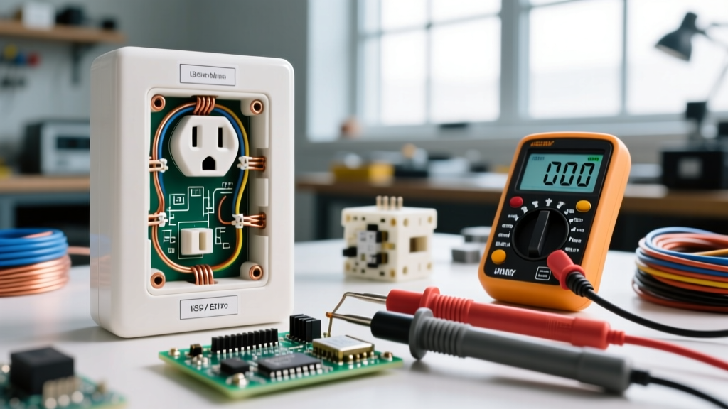
To accurately measure US electrical outlet voltage, you must abandon cheap, auto-parts-store multimeters. Professional diagnostics require True-RMS (Root Mean Square) meters capable of reading distorted waveforms from modern switching power supplies.
- Fluke 117 True-RMS Digital Multimeter ($190 - $210): The industry standard. Features Non-Contact Voltage (NCV) detection and, crucially, a LoZ (Low Impedance) mode to eliminate ghost voltage readings. Always verify your meter carries a CAT III 600V safety rating to protect against transient spikes at the panel.
- Klein Tools RT250 GFCI Receptacle Tester ($35 - $45): Used for rapid initial triage. While it cannot display exact voltage, its solenoid-based GFCI trip mechanism and neon light matrix quickly identify open neutrals, hot/ground reversals, and bootleg grounds before you insert multimeter probes.
- Weller ESD-Safe Insulated Probe Set ($25): Ensure probe tips are sharp enough to pierce heavy oxidation on older brass receptacle contacts without slipping and causing a phase-to-ground short.
The 3-Point Receptacle Testing Protocol
Measuring hot-to-neutral is only the first step. A comprehensive diagnosis requires three distinct measurements at the NEMA 5-15R receptacle. Set your multimeter to AC Voltage (V~) and insert the probes as follows:
1. Line (Hot) to Neutral
Insert the black probe into the shorter (hot) slot and the red probe into the longer (neutral) slot. Expected Reading: 118V - 122V. If this reads below 114V, you have a voltage drop issue caused by wire length, undersized gauge, or a loose termination.
2. Line (Hot) to Ground
Move the red probe to the U-shaped ground hole. Expected Reading: 118V - 122V. This reading should be nearly identical to the Hot-to-Neutral reading. If Hot-to-Ground is significantly higher than Hot-to-Neutral (e.g., 120V vs 112V), it indicates a heavily loaded neutral wire or a high-resistance fault on the neutral path back to the panel.
3. Neutral to Ground
Insert the black probe into the neutral slot and the red probe into the ground hole. Expected Reading: 0V to 1.5V. This is the most revealing test. The neutral and ground are bonded only at the main service panel. Any voltage measured here represents the actual voltage drop occurring on the neutral wire under load. If you read >2V, the circuit is overloaded, or there is a failing neutral bus bar connection. According to the NFPA 70 National Electrical Code, neutral conductors must be sized to handle the maximum unbalanced load without creating hazardous voltage differentials.
Diagnosing Critical Failure Modes
Scenario A: Severe Voltage Drop (Readings Below 110V)
When a 120V outlet reads 105V under load, you are experiencing severe voltage drop. This is common in older homes with 14 AWG wiring powering modern, high-inrush current appliances like window AC units or shop vacuums.
The Math: Voltage drop is calculated as V_drop = (2 × L × I × R) / 1000, where L is one-way wire length in feet, I is current in amps, and R is wire resistance per 1,000 feet. For 14 AWG copper, R is approximately 2.525 ohms. If you run a 15A space heater on a 75-foot 14 AWG circuit, the drop is (2 × 75 × 15 × 2.525) / 1000 = 5.68V. While 5.68V is within the 3% NEC recommendation for branch circuits, adding a 50-foot extension cord pushes the drop past 9V, plunging the outlet into ANSI Range B or Out of Range.
The Fix: Upsize the branch circuit wiring to 12 AWG (or 10 AWG for runs over 100 feet) and install a 20A breaker with a NEMA 5-20R receptacle.
Scenario B: The MWBC Open Neutral (Readings Above 130V)
CRITICAL SAFETY WARNING: If you measure anywhere from 130V to 240V at a standard 120V outlet, immediately shut off the main breaker. Do not touch any connected appliances. This indicates a floating neutral on a Multi-Wire Branch Circuit (MWBC).
An MWBC uses two hot legs (sharing opposite phases) and a single shared neutral. If the handle tie is missing, or an electrician disconnected the shared neutral pigtail at the panel while the circuit was live, the two 120V legs become a series circuit across 240V. Depending on the resistance of the appliances plugged into each leg, the voltage will divide unevenly. One room's outlets might drop to 85V (causing motors to stall and overheat), while the room on the other leg spikes to 155V, instantly destroying TVs, computers, and LED drivers.
The Fix: This requires an electrician to re-terminate the neutral at the panel bus bar and ensure a NEC-compliant handle tie (e.g., Eaton BRHT or Square D HOMHT) is installed on the twin breakers.
Scenario C: Ghost Voltage (Readings of 60V - 90V on Dead Outlets)
You are testing an outlet that you know is disconnected, yet your digital multimeter reads 72V. This is capacitive coupling, or 'ghost voltage.' High-impedance digital meters (typically 10 Megohms) are so sensitive that they read the electromagnetic field induced by adjacent live wires running in the same conduit or cable sheath.
The Fix: Switch your multimeter to LoZ (Low Impedance) mode. This engages an internal shunt resistor (typically 3 kilohms) that bleeds off the phantom capacitive charge, dropping the reading to a true 0.0V. For a deeper technical breakdown of this phenomenon, refer to the OSHA Electrical Safety Guidelines regarding proper testing equipment selection to prevent false-positive lockout/tagout verifications.
Utility vs. Electrician: The Escalation Matrix
When US electrical outlet voltage falls outside ANSI Range A, determining who is responsible for the fix saves time and money. Use this matrix to decide your next step:
| Measurement Location | Voltage Reading | Diagnosis & Responsible Party |
|---|---|---|
| Main Panel Service Lugs | 112V (Below Range A) | Utility transformer tap issue or undersized service drop. Call the Power Company (POCO). |
| Main Panel Service Lugs | 122V (Normal) | Utility supply is healthy. Issue is internal. Call an Electrician. |
| Branch Circuit Receptacle | 108V (Under Load) | Internal voltage drop, loose breaker termination, or undersized wire. Call an Electrician. |
| Branch Circuit Receptacle | 145V to 240V | Open neutral on MWBC or lost utility neutral. Shut off main, call Electrician or POCO immediately. |
Final Thoughts on Preventative Diagnostics
Troubleshooting US electrical outlet voltage is not just about fixing dead receptacles; it is about protecting thousands of dollars in modern electronics and preventing thermal events at loose connections. By adopting the 3-point testing protocol, understanding the math behind voltage drop, and recognizing the severe hazard of MWBC open neutrals, you elevate your diagnostic capabilities from amateur guesswork to professional-grade electrical forensics. Always prioritize safety, wear appropriate PPE when testing live circuits, and ensure your testing equipment is calibrated and CAT-rated for the environment.