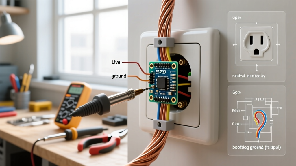

Mastering the Receptacle: Beyond Basic Installation
While learning how to connect electrical outlet wiring is a fundamental rite of passage for homeowners and junior electricians, the true test of expertise lies in diagnosing what happens when those connections fail. A standard 120V, 15A or 20A duplex receptacle seems simple: black to brass, white to silver, and bare copper to green. However, according to the Electrical Safety Foundation International (ESFI), electrical distribution and lighting equipment are consistently among the leading causes of residential fires. Many of these incidents stem from degraded terminations, hidden miswires, and ignored code violations.
As we navigate the 2026 National Electrical Code (NEC) landscape, the proliferation of dual-function AFCI/GFCI receptacles and stricter torque requirements mean that troubleshooting a dead or tripping outlet requires more than a simple neon tester. This guide shifts the focus from basic installation to advanced diagnostic workflows, equipping you to identify and resolve the most deceptive wiring faults found in modern residential circuits.
The 2026 Diagnostic Toolkit
To accurately diagnose outlet wiring faults, you must move beyond the $5 solenoid voltage tester. Professional troubleshooting requires precision instruments capable of measuring micro-ohms of resistance and detecting sub-voltage anomalies.
- True-RMS Digital Multimeter (e.g., Fluke 117): Essential for measuring exact AC voltage, continuity, and resistance. (Approx. $195)
- Advanced GFCI Receptacle Tester (e.g., Klein Tools RT250): Unlike basic 3-light testers, the RT250 features an LCD screen that identifies specific miswiring conditions, including bootleg grounds and line/load reversals. (Approx. $49)
- Calibrated Torque Screwdriver (e.g., Klein 32500TOR): NEC 110.14(D) mandates that terminations be tightened to the manufacturer's specified torque. A standard 15A receptacle typically requires 14 in-lbs of torque. (Approx. $110)
- Thermal Imaging Camera (e.g., FLIR C5): Used to detect resistive heating at terminal screws under load before a catastrophic failure occurs.
Decoding the Diagnostic Matrix
When an outlet appears dead or behaves erratically, your first step is to plug in an advanced receptacle tester. Below is the diagnostic matrix for interpreting the LCD readouts on standard testers like the Klein RT250 when evaluating a 120V circuit.
| Tester Display / LED Pattern | Identified Fault | Diagnostic Next Steps |
|---|---|---|
| CORRECT | Wiring is correct | Verify torque specs; test under 15A load for voltage drop. |
| OPEN GROUND | Missing equipment ground | Check panel ground bar; look for cut ground wires in the box. |
| OPEN NEUTRAL | Disconnected white wire | Inspect upstream junction boxes; check for failed backstab connections. |
| OPEN HOT | Disconnected black wire | Check breaker status; trace upstream daisy-chain for loose hot. |
| HOT/GND REVERSE | Black and Bare/Green swapped | Immediate danger. Remove power and swap conductors at the terminal. |
| BOOTLEG GROUND | Neutral jumpered to Ground | Remove receptacle; locate and remove the illegal jumper wire. |
Troubleshooting High-Resistance Terminations (The Backstab Failure)
One of the most common reasons homeowners search for how to connect electrical outlet replacements is that their existing outlets have melted or failed under load. This is almost always traced back to "backstab" or push-in wiring connections.
The Physics of Push-In Failures
Standard residential receptacles (like the ubiquitous Leviton 5362-W) feature push-in terminals on the back. These rely on a small brass leaf spring to grip 14 AWG solid copper wire. While UL-listed and code-compliant for 15A circuits, these springs are highly susceptible to thermal creep. When subjected to continuous loads near their 15A limit—such as space heaters, microwaves, or portable AC units—the terminal heats up. Over months of thermal expansion and contraction, the brass spring loses its tensile strength.
The result is a high-resistance joint. According to Ohm's Law, as resistance increases at the joint, power is dissipated as heat ($P = I^2R$). A thermal camera will often reveal terminal temperatures exceeding 160°F (71°C) just behind the plastic faceplate, eventually leading to arcing and melted polycarbonate housings.
The Diagnostic Fix
- Isolate the Circuit: Turn off the breaker and verify zero voltage.
- Extract the Wires: Insert a small flathead screwdriver or specialized release tool into the slot next to the wire to depress the spring and release the conductor.
- Inspect the Conductor: If the copper wire is pitted, blackened, or deeply grooved, cut it back to bare, shiny copper.
- Re-terminate Properly: Form a "sheep's hook" loop with needle-nose pliers. Hook the wire clockwise around the side terminal screw so that tightening the screw pulls the loop tighter.
- Upgrade the Hardware: For high-load areas, replace the standard receptacle with a commercial-specification back-wire clamp model (e.g., Leviton 5366), which uses a screw-actuated pressure plate rather than a fragile leaf spring.
GFCI Line vs. Load: The Most Common Miswire
With the 2026 NEC expanding Ground Fault Circuit Interrupter (GFCI) requirements to nearly all accessible 125V/250V receptacles, troubleshooting GFCI nodes is a daily necessity. The most frequent error when figuring out how to connect electrical outlet GFCI circuits is confusing the LINE and LOAD terminals.
Expert Insight: The LINE terminals bring power into the GFCI from the breaker panel. The LOAD terminals send protected power downstream to other standard receptacles. Reversing these will result in a GFCI that powers itself but provides no downstream protection, or a GFCI that refuses to reset entirely.
Diagnosing a Dead Downstream Circuit
If you have a GFCI receptacle that has power, but the standard outlets downstream are dead, follow this diagnostic flow:
- Use your multimeter to measure voltage between the Hot (black) and Ground (bare) wires at the upstream GFCI's LINE terminals. You should read ~120V.
- If the downstream outlets are dead, turn off the power and remove the GFCI.
- Inspect the LOAD terminals. Are the downstream wires connected to the LINE terminals alongside the source wires? (This is a code violation known as "double-tapping" on a standard receptacle screw, though some modern GFCIs allow two wires under the pressure plate).
- Ensure the downstream hot and neutral are connected only to the LOAD terminals, which are typically covered by a yellow warning sticker from the factory.
Unmasking the "Bootleg Ground" Deception
A bootleg ground occurs when an installer illegally connects a jumper wire between the neutral (silver) terminal and the ground (green) terminal on a receptacle. This is usually done in older homes with ungrounded 2-wire systems to trick a basic 3-light tester into reading "CORRECT" so a home inspector won't flag it.
This is incredibly dangerous. If a loose neutral occurs upstream, the metal chassis of any appliance plugged into that outlet will become energized with 120V, posing a lethal shock hazard.
How to Detect a Bootleg Ground
Basic testers cannot reliably detect a well-executed bootleg ground. To diagnose this, use your True-RMS multimeter:
- Step 1: Measure Hot to Neutral (H-N). Note the voltage (e.g., 121.5V).
- Step 2: Measure Hot to Ground (H-G). Note the voltage.
- Step 3: Measure Neutral to Ground (N-G).
- The Tell: In a properly wired circuit, H-G will be slightly lower than H-N due to normal voltage drop on the neutral wire, and N-G will read between 0.5V and 2.0V. If H-N and H-G are exactly identical down to the tenth of a volt, and N-G reads absolute 0.0V, you likely have a bootleg ground. The ground terminal is simply reading the neutral wire's potential.
- Confirmation: Turn off the breaker, remove the receptacle from the box, and visually inspect for a jumper wire or a continuous wire bridging the silver and green screws.
Torque Specifications: The Final Verification
Once you have diagnosed the fault, stripped the wires correctly, and re-terminated them on the side screws, your job is not finished. The 2026 NEC strictly enforces NFPA 70 Section 110.14(D), which requires terminations to be tightened to the manufacturer's specified torque.
Under-torqued screws will vibrate loose over time due to the thermal cycling of the copper wire, leading to arcing faults that standard breakers cannot detect. Over-torqued screws can strip the brass terminal threads or deform the wire, reducing the contact surface area and increasing resistance.
Set your calibrated torque screwdriver to the value printed on the receptacle's yoke or packaging (typically 14 in-lbs for 15A/20A devices). Tighten the screw until the tool clicks or slips. This single, often-ignored step is the hallmark of a professional installation and the ultimate safeguard against future thermal failures.
Summary
Knowing how to connect electrical outlet wiring is only half the battle. The ability to systematically diagnose open neutrals, identify deceptive bootleg grounds, and prevent high-resistance backstab failures separates amateur patch-jobs from safe, code-compliant electrical work. Always prioritize verified testing over visual assumptions, use the correct torque tools, and respect the expanded GFCI/AFCI requirements of the modern electrical code.