
Decoding the Standard Diagram of Electrical Outlet Wiring
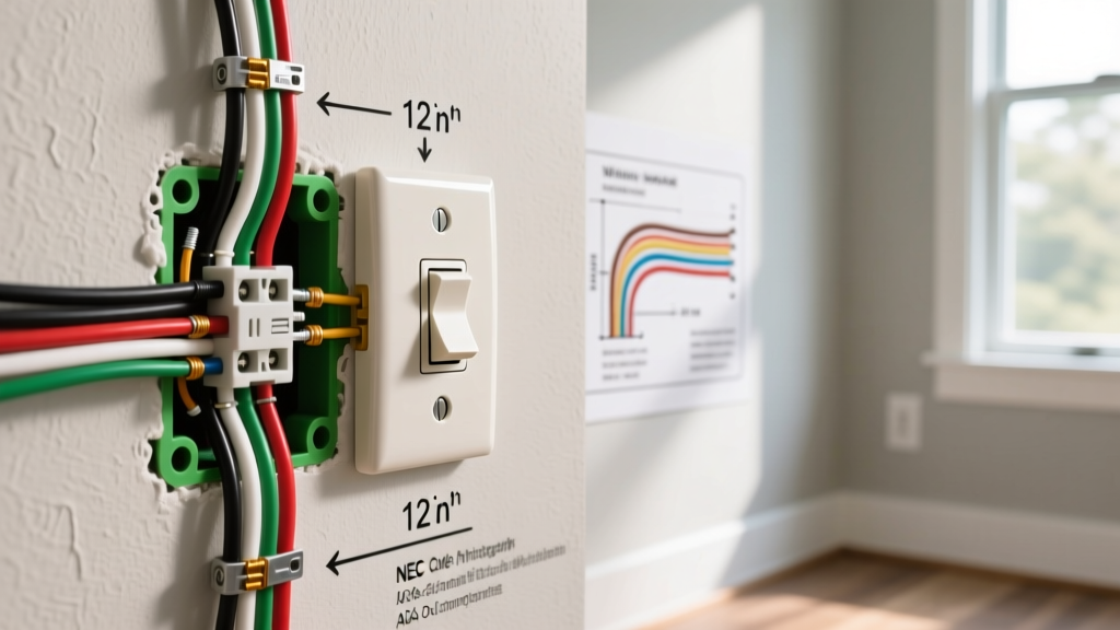
Whether you are replacing a damaged duplex receptacle, installing a new kitchen circuit, or troubleshooting a tripped breaker, understanding the fundamental diagram of electrical outlet wiring is a non-negotiable skill for any DIYer or apprentice electrician. While the physical act of connecting wires seems straightforward, the underlying topology dictates circuit continuity, ground-fault protection, and compliance with the latest National Electrical Code (NEC) standards.
In this comprehensive wiring diagram reference, we break down the exact terminal mappings, wire gauge requirements, and advanced configurations—including split-wired, GFCI, and Multi-Wire Branch Circuits (MWBC). According to the U.S. Consumer Product Safety Commission (CPSC), improper receptacle wiring remains a leading cause of residential electrical fires, often stemming from reversed polarity, open neutrals, or reliance on deprecated push-in back-stab connections.
Anatomy of a Standard Duplex Receptacle
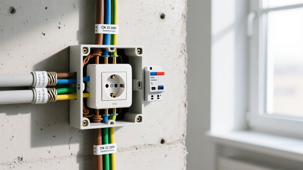
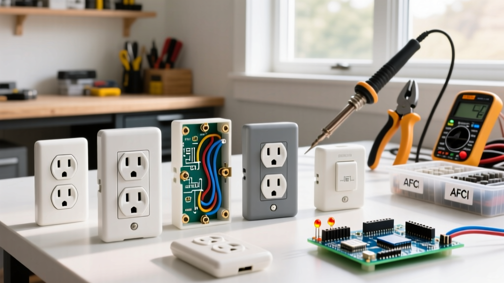
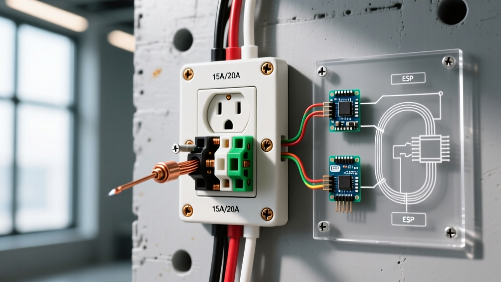
Before interpreting any diagram of electrical outlet configurations, you must understand the physical terminal layout of a standard NEMA 5-15R (15-Amp) or NEMA 5-20R (20-Amp) receptacle. Modern commercial-spec receptacles (such as the Leviton 5362 or Eaton 5754N) feature three distinct terminal zones:
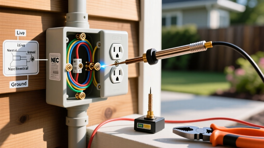
- Brass (Gold) Screws: The "Hot" or "Line" connection. Accepts black or red insulated wires.
- Silver Screws: The "Neutral" connection. Accepts white or gray insulated wires.
- Green Screw: The "Equipment Grounding Conductor" (EGC). Accepts bare copper or green insulated wires.
Crucially, the two brass screws and the two silver screws on a standard receptacle are joined by metal break-off fins (tabs). In a standard pass-through wiring diagram, these tabs remain intact, allowing power to enter on one set of screws and exit to the next downstream outlet on the other set.
Wire-to-Terminal Mapping Matrix
| Wire Color | Function | Terminal Screw | 15A Circuit (14 AWG) | 20A Circuit (12 AWG) |
|---|---|---|---|---|
| Black / Red | Ungrounded (Hot) | Brass | Yes | Yes |
| White / Gray | Grounded (Neutral) | Silver | Yes | Yes |
| Bare / Green | Equipment Ground | Green | Yes | Yes |
15A vs. 20A Receptacle Configurations
A common point of confusion when reading a wiring diagram is the difference between 15A and 20A receptacles. A 15A circuit utilizes 14 AWG copper wire and a 15A breaker, terminating in standard NEMA 1-15R or 5-15R receptacles. A 20A circuit requires 12 AWG copper wire and a 20A breaker.
According to NEC Article 210.21(B)(3), you can install standard 15A receptacles on a 20A circuit, provided there are two or more receptacles on the yoke (which a standard duplex outlet satisfies). However, if you are installing a single receptacle on a 20A circuit, it must be a 20A rated receptacle (NEMA 5-20R), identifiable by the T-shaped neutral slot. The wiring diagram for both remains identical regarding terminal connections; the difference lies strictly in the physical slot geometry and the minimum wire gauge feeding the circuit.
Advanced Diagram: Split-Wired (Half-Hot) Outlets
In living rooms and bedrooms, it is common to find a split-wired receptacle where the top half is controlled by a wall switch, and the bottom half remains constantly hot for devices like clocks or routers. To execute this diagram of electrical outlet wiring, you must alter the physical receptacle.
Step-by-Step Split-Wire Execution
- Break the Hot Tab: Using needle-nose pliers, snap off the small brass connecting fin between the two brass terminal screws. Never break the silver neutral tab on a standard split-wired circuit.
- Connect the Constant Hot: Attach the always-hot black wire to the bottom brass screw.
- Connect the Switched Hot: Attach the switched-leg red wire (or black wire with red tape) returning from the wall switch to the top brass screw.
- Terminate Neutral and Ground: Connect the white neutral wire to either silver screw (the silver tab remains intact) and the bare ground to the green screw.
GFCI Outlet Wiring: Line vs. Load Distinctions
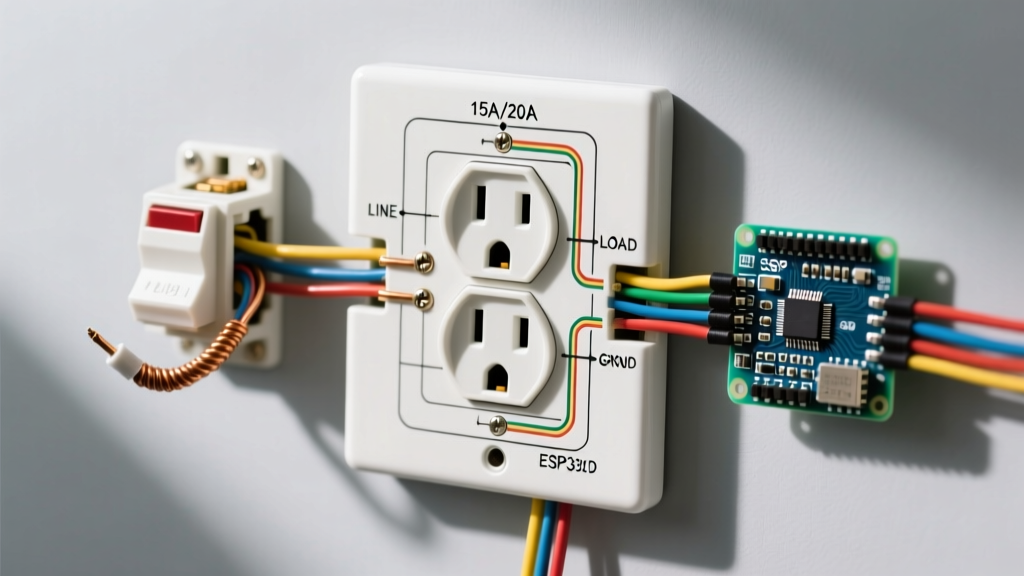
Ground Fault Circuit Interrupter (GFCI) receptacles, such as the Leviton GFNT2-W, introduce a critical variable to your wiring diagram: the distinction between LINE and LOAD terminals. Standard receptacles do not differentiate between incoming and outgoing wires, but GFCIs monitor the current differential between the hot and neutral conductors. If wired backward, the GFCI will reset and power the outlet, but it will not provide shock protection.
Downstream Protection Matrix
| Wiring Configuration | Terminals Used | Receptacle Protection | Downstream Protection |
|---|---|---|---|
| Single Location | LINE only | Yes | No (None connected) |
| Feed-Through | LINE and LOAD | Yes | Yes (Protects standard outlets downstream) |
| Reverse Wired (Error) | LOAD only | False Sense of Security | No |
Pro Tip: Always identify the LINE wires by turning on the breaker, testing the wires with a non-contact voltage tester (like the Klein Tools NCVT-4IR), and tagging them with black electrical tape before turning the power back off to make your final connections.
Multi-Wire Branch Circuits (MWBC) on Outlet Diagrams
Heavy-load areas like kitchens and garages often utilize Multi-Wire Branch Circuits. An MWBC diagram of electrical outlet wiring features two hot wires (typically black and red) sharing a single neutral (white) wire, fed by a 2-pole breaker or two single-pole breakers with an identified handle tie (NEC 210.4).
The critical rule for MWBC receptacle wiring is neutral pigtailing. Under NEC 300.13(B), the continuity of the grounded (neutral) conductor in an MWBC must not depend on the receptacle itself. If you were to daisy-chain the neutral through the silver screws and later remove the receptacle, you would open the shared neutral, potentially sending 240V across downstream 120V appliances, instantly destroying them. Always use a wire nut to connect the incoming neutral, outgoing neutral, and a short 6-inch pigtail to the receptacle's silver screw.
Pro-Tier Installation Standards for 2026
To ensure your installation meets the rigorous demands of modern electrical loads and passes municipal inspections, adhere to these expert-level installation metrics:
- Wire Stripping Length: Strip exactly 3/4 inch of insulation. Exposed copper beyond the terminal washer creates a shock hazard; too little insulation under the washer causes high-resistance arcing.
- Clockwise Looping: When using side-wiring, form a J-hook in the solid copper wire and loop it clockwise around the screw. As you tighten the screw clockwise, the loop will pull tighter rather than splaying open.
- Torque Specifications: The National Fire Protection Association (NFPA) and NEC 110.14(D) mandate that terminations be torqued to the manufacturer's specifications. For most commercial-grade 15A/20A receptacles, this is between 12 and 14 inch-pounds. Use a calibrated torque screwdriver to prevent loose connections that lead to thermal failure.
- Avoid Push-In Back-Stabbing: Never use the spring-loaded push-in holes on the back of 15A residential-grade receptacles. While UL-listed, they are prone to high-resistance failures under continuous 12A+ loads. Always use side-terminal screws or the screw-clamp back-wiring plates found on commercial-spec devices.
Troubleshooting Outlet Wiring with a Multimeter
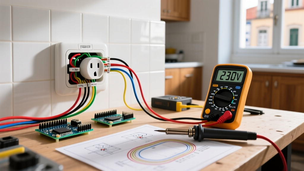
If your newly wired outlet is dead or tripping breakers, do not guess. Use a digital multimeter to verify the topology against your diagram. According to OSHA electrical safety guidelines, testing under load requires proper PPE and category-rated meters (CAT III minimum).
Safety Warning: Never assume a circuit is de-energized based solely on the breaker position. Always verify zero voltage at the receptacle terminals using a verified CAT III or CAT IV multimeter before touching bare conductors.
Standard Voltage Readings (120V Nominal System)
- Hot (Brass) to Neutral (Silver): ~120V. (If 0V, check for open breaker or open neutral). If ~240V, you have an open shared neutral on an MWBC.
- Hot (Brass) to Ground (Green): ~120V. (If 0V, you have an open ground or a bootleg ground wired to the neutral).
- Neutral (Silver) to Ground (Green): ~0V to 2V. (If reading >5V, you have a high-resistance neutral connection or an overloaded circuit causing voltage drop).
Final Thoughts on Receptacle Topology
Mastering the diagram of electrical outlet wiring extends far beyond matching colors to screws. It requires an understanding of circuit topology, NEC safety mandates, and the physical limitations of the hardware you are installing. By prioritizing torque-spec terminations, proper neutral pigtailing on shared circuits, and strict adherence to Line/Load designations on GFCI devices, you ensure a resilient, fire-safe electrical system that will perform reliably for decades.