
Understanding the Type A Electrical Outlet (NEMA 1-15R)
When electrical professionals and home inspectors refer to a Type A electrical outlet, they are referencing the ungrounded, two-slot receptacle formally classified as NEMA 1-15R. Designed to accept the IEC Type A (two-prong ungrounded) plug, these 15-amp, 125-volt devices were the standard in North American residential wiring prior to the 1960s. While modern construction mandates equipment grounding conductors (EGC), millions of Type A outlets remain in service across older homes, historic properties, and legacy commercial buildings.
From an inspection and testing perspective, Type A outlets present unique diagnostic challenges. Because they lack a dedicated ground slot, standard 3-prong receptacle testers cannot be used directly. Furthermore, the aging infrastructure behind these outlets—often cloth-insulated wiring, early BX armor cable, or degraded rubber—requires a meticulous, safety-first approach. This guide provides a comprehensive, professional-grade protocol for inspecting, testing, and evaluating Type A electrical outlets in 2026.
The Hidden Dangers of Aging Type A Receptacles
Before reaching for a multimeter, it is critical to understand the specific failure modes associated with ungrounded, legacy receptacles. According to the Electrical Safety Foundation International (ESFI), aging receptacles are a leading cause of residential arc faults and thermal runaway events.
- Loss of Contact Tension: Over decades of use, the internal brass wipers lose their spring tension. A plug that easily falls out of the socket creates high-resistance micro-arcing, generating extreme heat.
- Bakelite Degradation: Early Type A outlets were manufactured from Bakelite or urea-formaldehyde plastics. These materials become brittle over time, cracking internally and exposing live 120V terminals to the metal mounting strap or wooden framing.
- Paint Overspray and Debris: Decades of interior painting often result in layers of latex or oil-based paint inside the hot and neutral slots, increasing insertion resistance and causing localized melting.
- Push-In (Backstab) Failures: If a Type A outlet was replaced in the 1980s or 90s using push-in backstab connectors on 14 AWG wire, the internal spring clips are highly prone to fatigue, leading to open-neutral conditions.
Professional Tool Loadout for Ungrounded Circuits
Testing a Type A outlet requires tools that do not rely on an equipment ground for reference. Assemble the following diagnostic gear:
- Digital Multimeter (DMM): A True-RMS meter with CAT III 600V rating, such as the Fluke 117 Electricians True-RMS DMM (approx. $180). The non-contact voltage (NCV) and low-impedance (LoZ) modes are essential for detecting ghost voltages on floating neutrals.
- Non-Contact Voltage Tester: The Klein Tools NCVT-2 (approx. $35) allows for safe initial verification of the hot conductor without inserting probes into potentially brittle slots.
- Insulated Hand Tools: A VDE-rated or UL-listed insulated screwdriver set (e.g., Wiha 32095) rated for 1000V to safely remove faceplates and terminal screws.
- Receptacle Tension Tester: While optional for DIYers, professionals use a UL 498 compliant plug-pull gauge to verify that the withdrawal force meets the minimum 3-pound threshold.
Phase 1: Visual and Mechanical Inspection
Always begin with the circuit energized to perform non-invasive checks, then de-energize at the breaker panel for physical inspection.
1. The Tension and Alignment Test
Insert a standard 2-prong plug (such as a lamp cord) into the Type A outlet. If the plug slides in with zero resistance or hangs loosely by its own cord weight, the internal brass contacts are fatigued. Under the UL 498 standard, a receptacle must maintain sufficient grip to prevent accidental withdrawal. Action: Flag the receptacle for immediate replacement; do not attempt to bend the prongs to compensate.
2. Faceplate and Strap Integrity
Remove the faceplate and inspect the mounting strap. Look for signs of thermal discoloration (brown or black scorch marks) around the terminal screws. Check for paint bridging the gap between the hot slot and the mounting strap, which can create a tracking path for leakage current.
Phase 2: Digital Multimeter (DMM) Testing Protocol
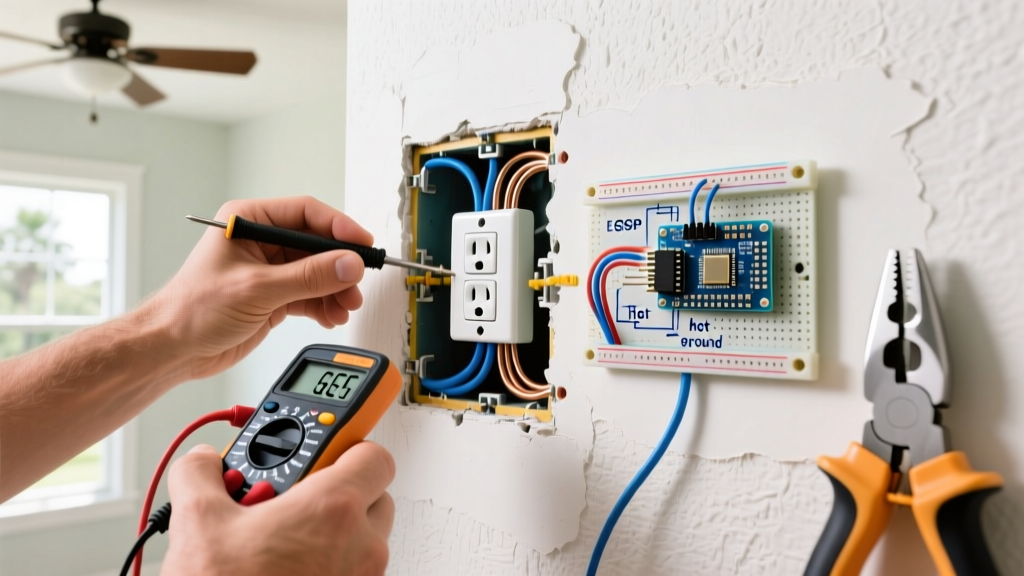
Because a Type A outlet lacks a ground slot, you must use the metal junction box (if present and properly bonded) or a known ground reference (like a nearby copper water pipe) to test for fault conditions. Set your Fluke 117 to AC Voltage (V~).
Step-by-Step Voltage Verification
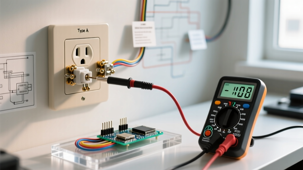
- Hot to Neutral: Insert the red probe into the shorter (hot) slot and the black probe into the longer (neutral) slot. Expected reading: 115V to 125V. If you read 0V, you have an open hot or open neutral. If you read ~240V, the neutral is severed and the circuit is feeding back through a 240V appliance elsewhere on the split-phase system.
- Hot to Ground Reference: Keep the red probe in the hot slot. Touch the black probe to the metal junction box or the center mounting screw. Expected reading: 115V to 125V. If the box is plastic or ungrounded, this will read 0V or a low 'ghost voltage' (which the LoZ mode on the Fluke 117 will eliminate).
- Neutral to Ground Reference: Move the red probe to the neutral slot and the black probe to the ground reference. Expected reading: Under 2.0V. A reading higher than 2V indicates a loose neutral connection upstream or an overloaded shared-neutral (Edison) circuit.
Diagnostic Voltage Matrix
| Test Points | Expected Reading | Fault Indication if Abnormal |
|---|---|---|
| Hot to Neutral | 115V - 125V | Open Neutral, Reverse Polarity, or Shared Neutral Overload |
| Hot to Metal Box | 115V - 125V | Ungrounded Box, Severed Armor Cable, or Open Hot |
| Neutral to Metal Box | 0V - 2.0V | High-Resistance Neutral, Bootleg Ground, or Crossed Wires |
| Slot Width Check | N/A (Visual) | Reverse Polarity if longer slot is Hot (severe shock hazard) |
The 'Bootleg Ground' Deception: A Lethal Edge Case
One of the most dangerous scenarios encountered during a Type A inspection is the 'bootleg ground.' This occurs when an unscrupulous DIYer or flipper replaces a 2-prong Type A receptacle with a 3-prong Type B (NEMA 5-15R) receptacle to pass a superficial home inspection, but wires a jumper between the neutral terminal and the ground screw.
Warning: A bootleg ground creates a massive shock hazard. If the neutral wire ever becomes disconnected upstream, the metal chassis of any plugged-in appliance (like a refrigerator or microwave) will become energized at a full 120V, using the user's body as the path to ground.
How to detect it without removing the outlet: Plug a high-wattage load (like a 1500W space heater) into the outlet. Use your DMM to measure the voltage between the Neutral slot and a known, verified ground (like a plumbing pipe). If the voltage rises significantly (e.g., above 3V-5V) under load, current is flowing on the ground path, indicating a bootleg jumper. To confirm, de-energize the circuit, remove the faceplate, and visually inspect for a bare copper or green jumper wire connecting the silver neutral screw to the green ground screw.
NEC Code Compliance and 2026 Upgrade Paths
When inspecting Type A outlets, you must evaluate them against current safety standards. According to Electrical Construction & Maintenance (EC&M) and NEC Article 406.4(D), you are not required to tear open walls to run new equipment grounding conductors in existing older homes. However, if a Type A outlet is damaged and needs replacement, you have three code-compliant options:
- Replace with a like-for-like Type A (NEMA 1-15R): This is legal but increasingly impractical, as modern appliances and power strips require 3-prong grounded connections.
- Replace with a GFCI Receptacle: You can install a Ground Fault Circuit Interrupter (e.g., Leviton SmartlockPro GFNT1, approx. $28). The GFCI does not require an equipment ground to function; it monitors the current differential between hot and neutral. Crucial Step: You must apply the included 'No Equipment Ground' and 'GFCI Protected' stickers to the faceplate. Note that this provides shock protection, but does not provide a clean ground for sensitive electronics or surge protectors.
- Install an AFCI/GFCI Dual-Function Breaker: For 2026 compliance in living areas and bedrooms, upgrading the branch circuit breaker to a Dual-Function (DF) AFCI/GFCI breaker allows you to install standard 3-prong receptacles downstream, provided they are marked 'No Equipment Ground'. This protects the entire legacy wiring run from arc faults caused by degrading cloth insulation.
Final Torque and Termination Standards
If your inspection dictates that the Type A outlet must be replaced or re-terminated, abandon the push-in backstab method entirely. Strip the 14 AWG or 12 AWG copper wire to the manufacturer's strip gauge, form a proper shepherd's hook, and loop it clockwise around the terminal screw. Using a torque screwdriver set to the manufacturer's specification (typically 14 in-lbs for Leviton and Hubbell residential devices) ensures the connection will not loosen due to thermal expansion and contraction cycles over the next decade.
By adhering to this rigorous inspection and testing protocol, you ensure that legacy Type A electrical outlets are either verified as safe for continued low-load use or upgraded to meet modern shock and arc-fault protection standards. For further reading on residential electrical safety and code updates, consult the National Fire Protection Association (NFPA) resources on NFPA 70 (National Electrical Code).