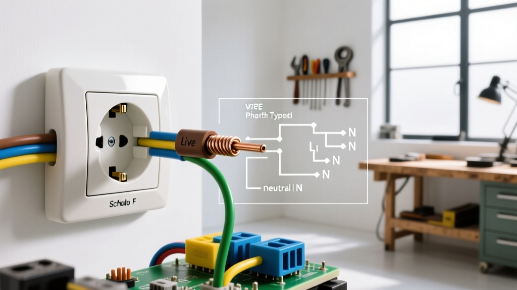

Why Upgrading Your Receptacles Matters
If you are researching how to change electrical outlet hardware in your home, you are likely dealing with loose-fitting plugs, discolored faceplates, or outdated two-prong designs. A worn-out 15-amp duplex receptacle isn't just an annoyance; it is a documented fire hazard. According to the National Fire Protection Association (NFPA), loose electrical connections and degraded receptacle contacts are leading causes of residential electrical fires. Replacing a standard outlet is a highly manageable DIY task, provided you respect the circuit, use the correct torque, and follow modern code requirements.
Project Snapshot: Time, Cost, and Skill Level
| Metric | Details |
|---|---|
| Skill Level | Beginner (with strict adherence to safety protocols) |
| Time Required | 20 to 35 minutes per receptacle |
| Material Cost | $2.50 - $6.00 per Leviton 15A TR Receptacle |
| Professional Cost | $150 - $250 (Electrician minimum call-out fee in 2026) |
Essential Tools and Materials for 2026
Do not attempt this project with a dull pocket knife or a cheap multi-tester. Precision and verification are your best defenses against arc faults and shocks.
- Non-Contact Voltage Tester (NCVT): Fluke 1AC-II VoltAlert (Approx. $35). Essential for initial dead-circuit verification.
- Digital Multimeter: Klein Tools MM400 or similar. Required to verify zero potential between Line, Neutral, and Ground.
- Wire Strippers: Klein Tools 11055 (10-18 AWG). Features a dedicated 5/8-inch stripping hole for perfect receptacle leads.
- Receptacle: Leviton R52-05320-WMP (15-Amp, 125-Volt, Tamper-Resistant, Duplex).
- Connectors: WAGO 221 Lever-Nuts (Assortment). Ideal for pigtailing grounds and neutrals without bulky twist-on wire nuts.
- Torque Screwdriver: Klein Tools 70900 or a specialized electrical torque driver calibrated to 14 in-lbs.
Safety Protocol: Verifying the Circuit is Dead
The Electrical Safety Foundation International (ESFI) emphasizes that relying solely on a wall switch or a single tester is a fatal beginner mistake. Follow the 'Test-Before-Touch' methodology:
- Kill the Breaker: Turn off the specific 15A or 20A breaker at your main service panel. If your panel is unlabeled, turn off the main breaker to be safe.
- Initial NCVT Scan: Insert your Fluke VoltAlert into the top and bottom slots of the outlet. The LED should remain dark.
- Multimeter Verification: Set your multimeter to AC Voltage (V~). Insert the black probe into the Neutral (left slot) and the red probe into the Line (right slot). The reading must be exactly 0.0V. Next, test Line to Ground (the round U-shaped hole). Again, 0.0V. This proves the circuit is truly de-energized and eliminates the risk of a shared-neutral backfeed.
Step-by-Step: How to Change Electrical Outlet Wiring
Step 1: Extraction and Inspection
Remove the center faceplate screw and pull the cover off. Unscrew the top and bottom mounting straps holding the receptacle to the electrical box. Gently pull the device out. Do not yank the wires. Inspect the copper conductors. If the insulation is cracked, brittle, or if the copper is deeply scored or oxidized (blackened), you must cut the damaged portion back and re-strip the wire.
Step 2: Prepping the Conductors
Using your Klein 11055 strippers, strip exactly 5/8 of an inch of insulation from the black (Line), white (Neutral), and bare (Ground) wires. The Leviton receptacle features a built-in strip gauge on the back of the yoke; use it to verify your length. Exposed copper beyond the terminal screw creates a short-circuit risk; too little copper inside the terminal creates a high-resistance hot spot.
Step 3: The Side-Wiring Technique (The Only Correct Way)
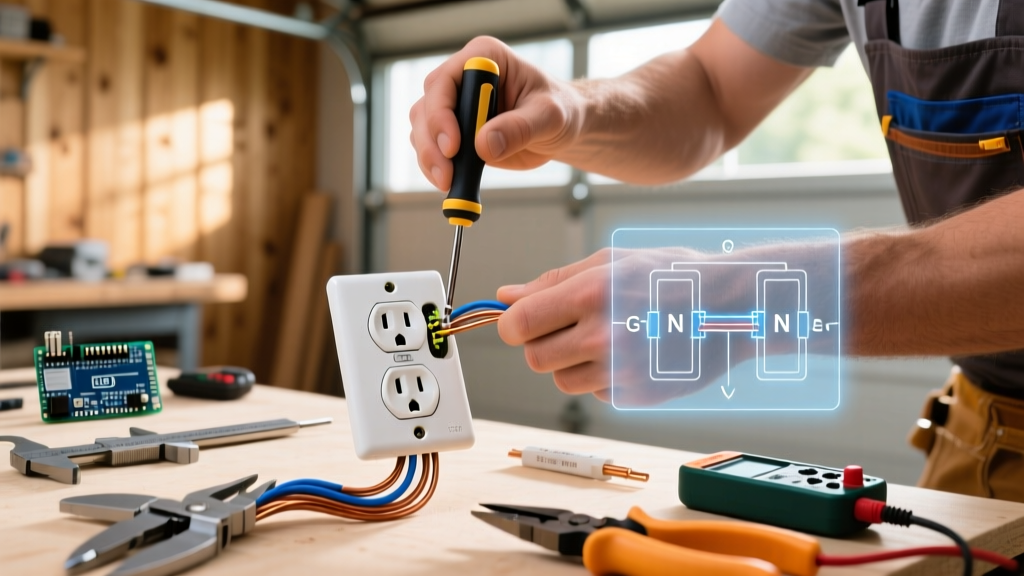
Form a tight 'J-hook' at the end of your stripped wire using the needle-nose pliers built into your wire strippers. The Golden Rule: Loop the J-hook clockwise around the terminal screw. When you tighten the screw (clockwise), the screw head will pull the wire loop tighter. If you loop it counter-clockwise, tightening the screw will push the wire out from under the head.
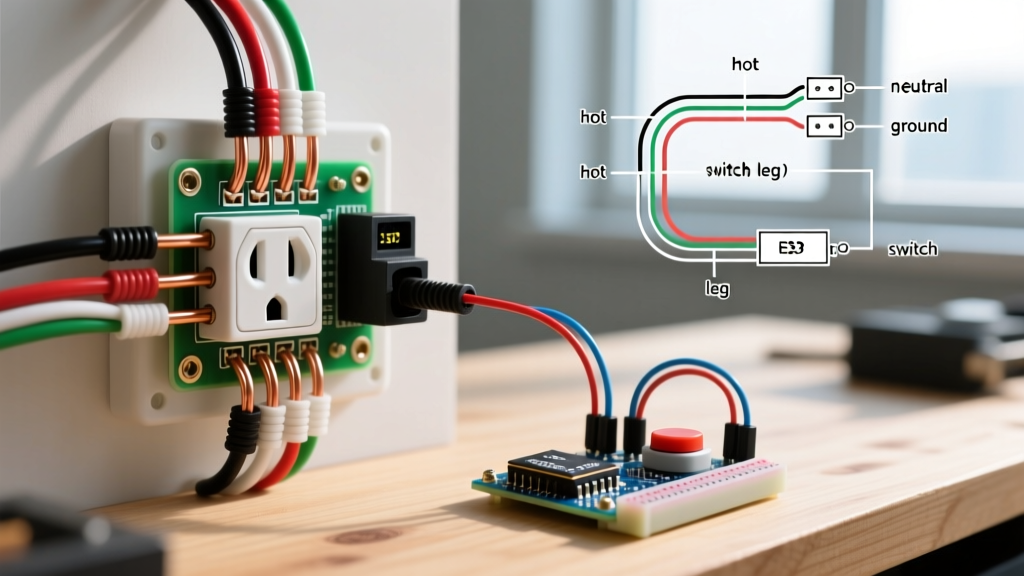
- Black (Hot) Wire connects to the Brass screw.
- White (Neutral) Wire connects to the Silver screw.
- Bare (Ground) Wire connects to the Green screw.
Step 4: Torque and Mounting
Tighten the terminal screws until the wire is firmly seated, then use your torque screwdriver to apply exactly 14 inch-pounds of torque. Under-torqued connections cause arcing and heat buildup over time, while over-torquing can snap the screw head or strip the brass threads. Once torqued, fold the wires neatly into the box (ground wires pushed to the back, neutrals to the sides, hots on top) and secure the yoke to the box.
Expert Warning: Never Use 'Back-Stab' Push-In Terminals
Beginners are often tempted by the quick-insert holes on the back of cheap receptacles. These spring-loaded 'back-stab' connections are notorious for failing. Thermal expansion and contraction from daily electrical loads cause the internal spring grips to loosen over time, leading to high-resistance connections, melted plastic yokes, and arc faults. Always use side-wiring (screw terminals) or, if the receptacle supports it, back-wiring via the internal screw-clamp plates.
Understanding Pigtailing vs. Daisy Chaining
If your electrical box contains two sets of black and white wires (one coming from the panel, one continuing to the next room), you have a 'daisy-chained' circuit. While you can wire both sets directly to the receptacle's four side screws, best practice in 2026 dictates using a pigtail.
How to Pigtail: Connect the two incoming white wires together with a third short white wire (the pigtail) using a WAGO 221 Lever-Nut. Connect the other end of the pigtail to the receptacle's silver screw. Repeat for the black wires and the bare ground wires. Pigtailing ensures that if this specific outlet ever fails or is removed for drywall work, the downstream rooms will not lose power.
2026 NEC Code Requirements You Must Know
When learning how to change electrical outlet hardware, you must upgrade to current National Electrical Code (NEC) standards, not just replicate the old 1980s installation.
- Tamper-Resistant (TR) Receptacles: Under NEC Article 406.12, all 15A and 20A receptacles in dwelling units must be Tamper-Resistant. TR outlets feature internal spring-loaded shutters that only open when equal pressure is applied to both slots simultaneously (like a plug prong). This prevents children from inserting foreign objects.
- AFCI Protection: If you are replacing an outlet in a bedroom, living room, or hallway, the circuit must be protected by an Arc-Fault Circuit Interrupter (AFCI) breaker. If your panel lacks AFCI, you may need to install an AFCI receptacle at the first point of the circuit.
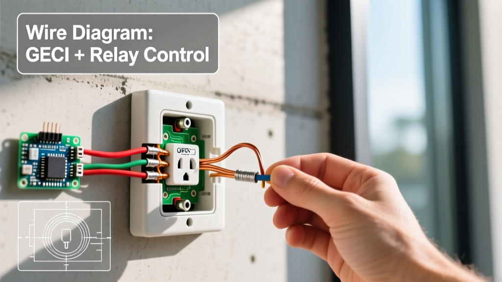
- GFCI Protection: Kitchens, bathrooms, garages, and outdoor receptacles require Ground-Fault Circuit Interrupter (GFCI) protection. If replacing a standard outlet in these zones, you must upgrade to a GFCI receptacle model (e.g., Leviton GFNT1-W).
Troubleshooting Common Beginner Mistakes
| Symptom | Root Cause | The Fix |
|---|---|---|
| Breaker trips immediately upon resetting | Line and Ground wires are touching, or a hot wire is pinched against the metal box. | Inspect the box for bare copper touching metal. Wrap the receptacle yoke sides with high-quality electrical tape (3M Super 33+) to insulate the terminal screws. |
| Outlet works, but downstream rooms are dead | Used back-stab terminals on a 'daisy-chained' wire, or forgot to connect the second set of Line/Neutral wires. | Turn off power, remove the outlet, and use WAGO Lever-Nuts to pigtail both sets of wires to a single lead going to the receptacle. |
| Faceplate bows outward or won't sit flush | The electrical box is set too far out from the drywall, or the mounting straps are bent. | Install a plastic receptacle spacer ring behind the yoke to bridge the gap, or replace the device with a deeper-mud-ring setup. |
| Voltage reads 120V, but plugging in a lamp causes flickering | High resistance connection due to under-torqued terminal screws or stripped insulation inside the clamp. | Re-strip the wire to ensure clean copper, re-form the J-hook, and torque to exactly 14 in-lbs. |
Final Verification
Once the outlet is mounted and the faceplate is secured, turn the breaker back on. Plug in a simple receptacle tester (like the Klein Tools RT210). The tester's LED lights will confirm that the wiring is correct, the ground is bonded, and the polarity (Hot to Brass, Neutral to Silver) is accurate. By following these precise, code-compliant steps, you ensure your home's electrical system remains safe, efficient, and up to modern 2026 standards.