
Diagnosing the Dead Receptacle: Beyond the Breaker Box
When you discover an electrical outlet plug is not working, the immediate assumption is often a tripped breaker. However, modern residential wiring involves multiple layers of protection and physical termination points that can fail independently. According to the Electrical Safety Foundation International (ESFI), faulty receptacles and loose wiring connections are leading causes of residential electrical fires. Diagnosing a dead outlet requires moving past simple visual checks and utilizing systematic multimeter testing to identify high-resistance faults, open neutrals, or degraded internal contacts.
Safety Directive: Never assume a receptacle is de-energized just because a plugged-in device lacks power. Always verify the absence of voltage using a non-contact tester before removing the faceplate. Lethal 120V/240V potential may still be present on the line-side terminals.
Phase 1: Non-Contact Voltage Triage
Before unfastening a single screw, you must establish the electrical state of the circuit. Using a reliable non-contact voltage (NCV) tester like the Fluke 1AC-II (approx. $30) or the Klein Tools NCVT-2 (approx. $25), probe the top and bottom slots of the dead outlet.
- No Beep/Flash: The circuit is likely de-energized, or you have an open hot wire upstream. Proceed to Phase 2.
- Continuous Beep: Voltage is present at the terminals, but the internal brass contacts have lost tension and are failing to grip the plug prongs. The receptacle requires immediate replacement.
- Intermittent/Weak Signal: Indicates a high-resistance connection, often caused by a 'backstabbed' wire that is arcing or slowly burning out inside the wall cavity.
Once the NCV tester confirms the absence of voltage (and you have verified the tester on a known live source), turn off the corresponding circuit breaker, lock it out if possible, and remove the duplex receptacle from the junction box.
Phase 2: Visual Inspection and the 'Backstab' Failure Mode
Pull the receptacle out gently, keeping the wires attached. The most common culprit for a prematurely failing 15A or 20A receptacle is the use of push-in backwire connectors (often called 'backstabbing').
Why Backstabbed Connections Fail
Push-in terminals rely on a small, spring-loaded brass clip to grip the stripped 14 AWG copper wire. Under continuous thermal cycling—such as when running a 12A to 15A space heater or window AC unit—the metal expands and contracts. Over 3 to 5 years, the spring tension degrades. The wire loosens, creating a micro-gap. This gap causes electrical arcing, which melts the surrounding polycarbonate housing and eventually results in an open circuit. If you see 14 AWG or 12 AWG wires shoved into the back holes of a standard builder-grade receptacle (like the basic Leviton 5320-W), you have found your failure point.
Phase 3: Multimeter Diagnostics and Voltage Matrix
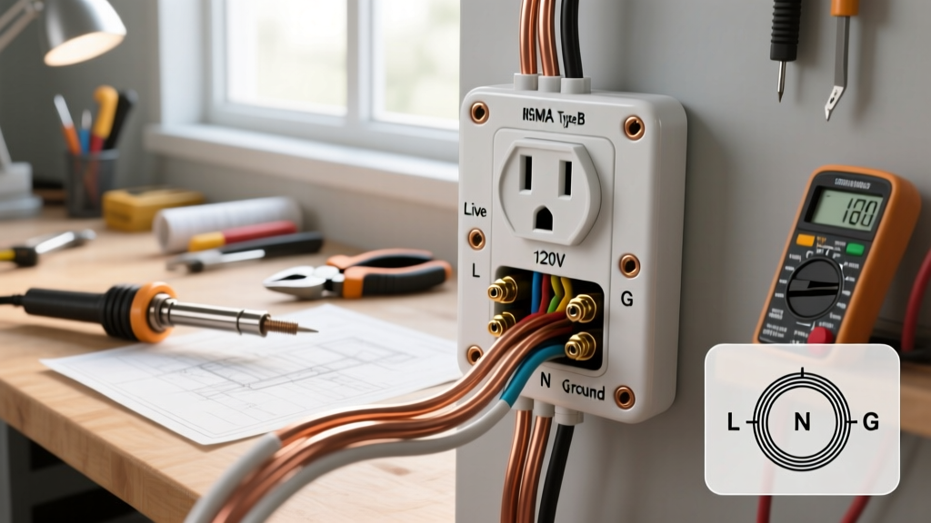
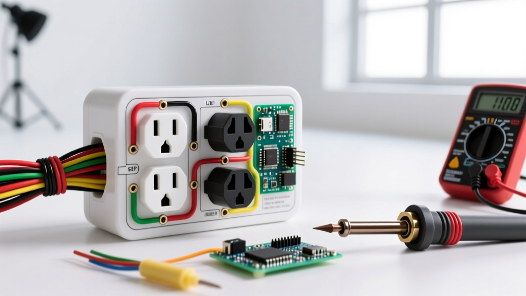
If the visual inspection reveals secure screw-terminal connections but the outlet is still dead (or if you are testing a live circuit to find a voltage drop), you need a digital multimeter (DMM) like the Klein Tools ET40 ($35) or the professional-grade Fluke 115 ($220). Set the DMM to AC Voltage (V~) and test the following combinations at the receptacle slots.
| Probe Placement | Expected Reading | Diagnostic Meaning of Deviation |
|---|---|---|
| Hot (Short Slot) to Neutral (Long Slot) | 114V - 126V | 0V: Open Hot or Open Neutral. <110V: High resistance fault or overloaded shared neutral. |
| Hot (Short Slot) to Ground (U-Shape) | 114V - 126V | 0V: Open Ground or Open Hot. 60V-80V: Induced phantom voltage (floating ground). |
| Neutral (Long Slot) to Ground (U-Shape) | 0V - 2V | 120V: Reversed Polarity (Hot/Neutral swapped). 5V-10V: Heavy load on the circuit causing neutral voltage rise. |
Note: Standard US utility voltage is 120V, but the ANSI C84.1 standard permits a utilization range of 114V to 126V. Readings consistently below 114V under load indicate a serious wiring defect upstream.
Phase 4: Upstream Edge Cases (GFCI and MWBC)
If your multimeter reads 0V across all terminals and the breaker is firmly in the ON position, the issue is upstream. Two specific scenarios frequently cause this:
1. The Hidden Upstream GFCI
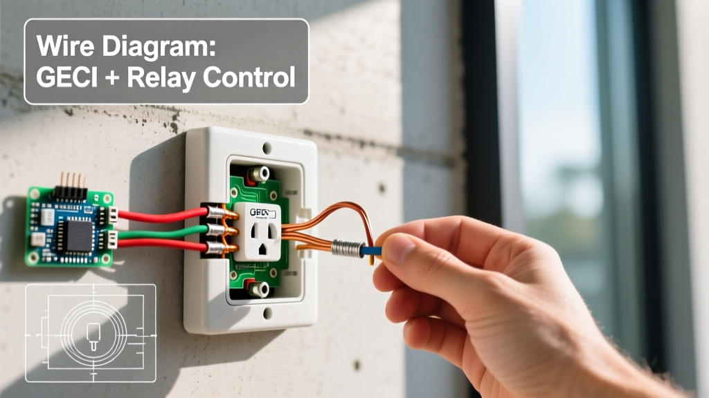
Modern electrical codes require Ground Fault Circuit Interrupter (GFCI) protection in wet areas and increasingly in all 15A/20A 125V receptacles. A standard receptacle in a living room or bedroom may be wired to the LOAD terminals of a GFCI receptacle located in a nearby bathroom, garage, or exterior wall. If that upstream GFCI trips, all downstream 'standard' outlets will lose power. Always map your GFCI reset points before tearing into drywall.
2. Multi-Wire Branch Circuits (MWBC)
In an MWBC, two hot wires (usually black and red) share a single white neutral wire, connected to opposite legs of the 120/240V split-phase panel. If a previous DIYer replaced a receptacle on an MWBC and failed to break off the brass hot-side fin tab, or if the handle-tied breaker was replaced with two independent single-pole breakers, you can experience a dead leg or a severely overloaded shared neutral. If you see a 3-wire cable (Black, Red, White, Bare) entering the box, verify the breaker configuration in the main panel immediately.
Phase 5: Code-Compliant Replacement and Torque Specs
When replacing a failed receptacle, discard builder-grade models. Upgrade to a commercial-specification or heavy-duty residential model, such as the Leviton T5262 (15A Tamper Resistant, approx. $3.50) or the Hubbell 5262 (20A Commercial Grade, approx. $6.00). These feature thicker internal brass contacts and robust steel mounting straps.
NEC Torque Requirements
As enforced in the NFPA 70 National Electrical Code (NEC) under section 110.14(D), all electrical terminations must be tightened using a calibrated torque tool to the manufacturer's specified values. While many DIYers simply 'crank it down,' over-torquing strips the brass screw threads, while under-torquing leads to thermal expansion failures.
- Standard 15A/20A Receptacles: Typically require 14 in-lbs (inch-pounds) of torque.
- Wire Preparation: Use the strip gauge on the back of the receptacle. For 14 AWG and 12 AWG solid copper, this is usually exactly 5/8 of an inch. Do not leave bare copper exposed outside the terminal, and do not allow insulation to be trapped under the brass screw head.
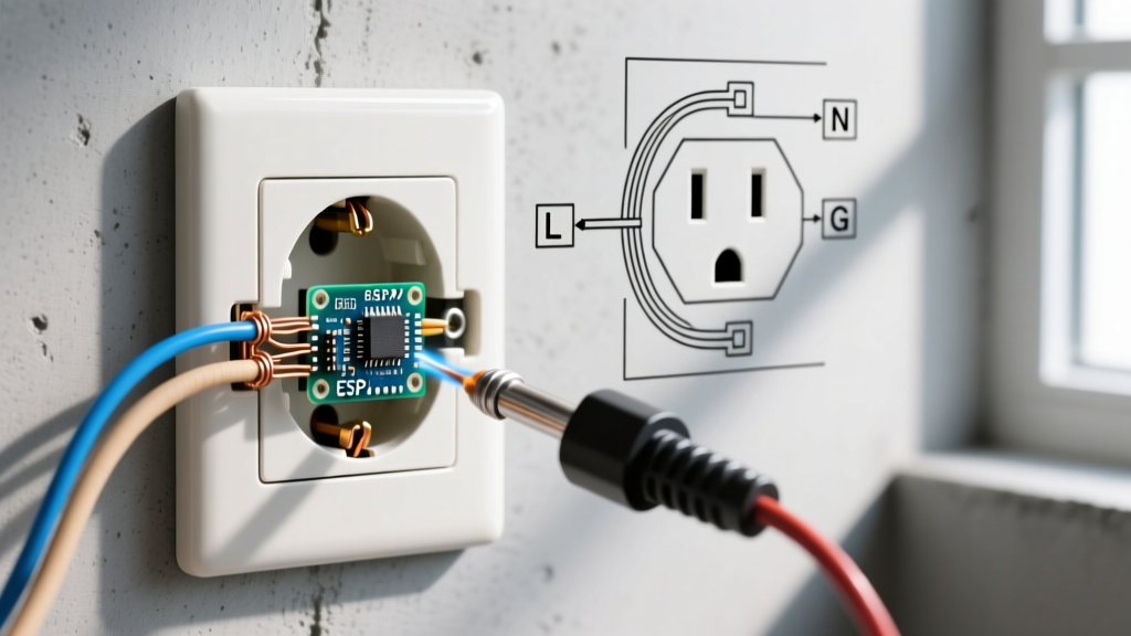
- Terminal Dressing: Form the wire into a fishhook, loop it clockwise around the screw (so tightening the screw pulls the loop closed), and tighten with a torque screwdriver like the Wiha 11150 TorqueVario-S or a dedicated Klein Tools LBCR14 preset torque driver.
For comprehensive safety standards regarding lockout/tagout and live-circuit testing, always refer to OSHA Electrical Safety Standards before undertaking commercial or high-amperage diagnostics.
Summary Checklist for the DIY Electrician
- Verify the device plugged in is functional (test on a known live circuit).
- Check for tripped upstream GFCI receptacles and AFCI breakers.
- Use an NCV tester to confirm the presence or absence of voltage at the slots.
- De-energize the circuit, remove the receptacle, and inspect for backstabbed wires or melted polycarbonate.
- Perform Hot-Neutral, Hot-Ground, and Neutral-Ground multimeter tests if diagnosing voltage drops.
- Replace failed units with commercial-grade, tamper-resistant receptacles, terminating wires via screw or side-clamp backwire using a calibrated torque driver.