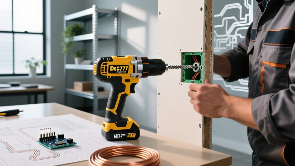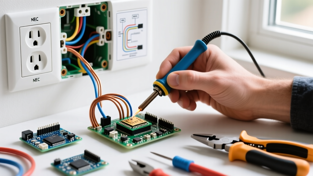

Upgrading your home's electrical wiring outlets is one of the most impactful safety and aesthetic improvements you can make. Whether you are replacing worn-out 15-amp receptacles, upgrading ungrounded 2-prong outlets, or ensuring compliance with the latest National Electrical Code (NEC) standards, this home project guide provides the exact specifications, tool requirements, and step-by-step procedures needed for a professional-grade installation.
Why Upgrade Your Electrical Wiring Outlets?
Many homes built before 2010 feature receptacles with degraded internal contacts or rely on "backstabbed" push-in wire connections. According to the Electrical Safety Foundation International (ESFI), loose connections at receptacles are a leading cause of residential electrical fires. Push-in backstab connections, which rely on a small spring-metal clip to hold the wire, are notorious for developing high-resistance faults over time, especially on 15-amp circuits powering high-draw appliances like space heaters or vacuum cleaners. Upgrading to side-wired, tamper-resistant receptacles eliminates this hidden fire hazard.
Safety Warning: Never work on live circuits. Always verify the absence of voltage using a reliable non-contact voltage tester and a plug-in circuit analyzer before touching any bare wires.
Essential Tools and Material Costs
To execute this project to professional standards, you need more than just a screwdriver. The 2023 NEC (widely adopted into 2026 local codes) mandates specific torque values for terminal screws under Article 110.14(D). Here is the exact bill of materials and tooling required for a modern upgrade:
| Item | Specific Model / Type | Estimated Cost (2026) | Purpose |
|---|---|---|---|
| Non-Contact Voltage Tester | Fluke 2AC-II VoltAlert | $35.00 | Initial live circuit detection |
| Plug-In Circuit Analyzer | Sperry ET6402 | $18.00 | Verifying wiring topology and GFCI trip |
| Wire Strippers | Klein Tools 11063W (10-22 AWG) | $28.00 | Clean stripping without nicking copper |
| Torque Screwdriver | Klein Tools 69054 | $45.00 | Meeting NEC 110.14(D) torque specs |
| 15A TR Receptacle | Leviton T5320-WST (Decora) | $3.50 / ea | Tamper-resistant, side-wire capable |
| 20A TR Receptacle | Leviton T5262-WST (Decora) | $4.25 / ea | Required for kitchen/bath small appliance circuits |
| Lever Nuts | Wago 221 Series (3-Port) | $0.65 / ea | Secure, reusable pigtail splicing |
Step-by-Step Replacement Procedure
Step 1: Isolation and Verification
Turn off the corresponding breaker at the main panel. Use the Fluke 2AC-II to scan the outlet faceplate. Remove the cover plate and unscrew the receptacle from the electrical box. Pull the receptacle out gently and test the side terminal screws with the NCVT. Finally, plug the Sperry ET6402 into a neighboring outlet on the same circuit to guarantee the breaker is correctly labeled and the circuit is fully de-energized.
Step 2: Wire Preparation and Inspection
If the existing wires are inserted into the backstab holes, use a small flathead screwdriver to release the internal spring clip. Never simply pull the wire out, as this can damage the copper conductor. Inspect the wire insulation for heat damage or melting. If the copper is pitted or blackened, cut it back to clean metal. Use the Klein Tools strippers to remove exactly 3/4 inch of insulation, matching the strip gauge printed on the back of your new Leviton receptacle.
Step 3: Pigtailing vs. Side-Wiring
Avoid using the receptacle as a splice point for downstream outlets. If the electrical box contains two sets of cables (one line, one load), create a "pigtail" splice. Connect the two black wires and a 6-inch black jumper wire using a Wago 221 lever nut. The clear housing of the Wago connector allows you to visually verify that all wires are fully seated. Connect the jumper to the brass (hot) terminal. Repeat for the white (neutral) wires and the silver terminal. This ensures that a loose terminal screw on the receptacle does not kill power to downstream rooms.
Step 4: Terminal Torque and Mounting
Loop the bare copper wire clockwise around the green ground screw. For the hot and neutral wires, insert them under the side terminal plates (never use the backstab holes). Tighten the screws using your torque screwdriver set to the manufacturer's specification—typically 14 in-lbs for standard Leviton 15A/20A devices. When folding the wires into the box, use an accordion-style fold rather than simply shoving them in. This prevents the ground wire from getting pinched behind the receptacle yoke, which could cause a dead short when you tighten the cover plate.
NEC Code Requirements for Receptacles
When upgrading electrical wiring outlets, you must bring the installation up to current code if you are altering the circuit or performing a major renovation. The National Fire Protection Association (NFPA) outlines strict requirements for receptacle placement and protection.
| Location | Circuit Rating | Protection Required | Device Type |
|---|---|---|---|
| Kitchen Countertops | 20-Amp Minimum | GFCI & AFCI | 20A Tamper-Resistant (TR) |
| Bathrooms | 20-Amp Minimum | GFCI | 20A TR |
| Living Rooms / Bedrooms | 15A or 20A | AFCI | 15A or 20A TR |
| Garages & Outdoors | 20-Amp Minimum | GFCI | 20A TR & Weather-Resistant (WR) |
| Laundry Areas | 20-Amp Dedicated | GFCI & AFCI | 20A TR |
Troubleshooting Common Wiring Faults
After restoring power, test the new outlet with your plug-in analyzer. Here is how to interpret and fix common fault indications:
- Open Neutral: The white wire is disconnected or broken. Check your pigtail connections and ensure the wire is fully seated under the silver terminal plate.
- Reversed Polarity: The hot (black) and neutral (white) wires are swapped. The brass screw must always receive the black wire; the silver screw receives the white wire.
- Bootleg Ground: Common in older homes where a jumper wire was illegally placed between the neutral and ground terminals to trick a 3-light tester. This is incredibly dangerous, as a neutral fault will electrify the metal chassis of any plugged-in appliance. Remove the jumper and leave the ground terminal empty if no true equipment grounding conductor exists in the box, replacing the outlet with a GFCI receptacle labeled "No Equipment Ground" as permitted by the NEC.
Edge Case: Handling Aluminum Branch Wiring
If your home was built between 1965 and 1973, you may encounter aluminum branch wiring. Standard copper-rated receptacles will oxidize and overheat when connected directly to aluminum wire. You must use receptacles specifically rated for aluminum (marked CO/ALR) or, preferably, pigtail the aluminum wire to copper using an AL8CU or purple wire nut, or an AlumiConn lug connector, before attaching it to a standard copper-rated TR receptacle. Never use standard IDEAL wire nuts on aluminum-to-copper splices.
Frequently Asked Questions
Can I install a 20-amp receptacle on a 15-amp breaker?
Yes. The NEC permits 20-amp rated receptacles (which feature a T-shaped neutral slot) on 15-amp circuits, provided it is a single receptacle on a single branch circuit. However, standard practice for multiple receptacles on a 15-amp circuit is to use 15-amp devices. Never install a 15-amp receptacle on a 20-amp circuit, as this violates NEC 210.21(B)(3) and creates an overload hazard.
What does "Tamper-Resistant" (TR) mean, and is it mandatory?
TR receptacles feature internal spring-loaded shutters that only open when equal pressure is applied to both slots simultaneously (like a plug's prongs). According to the Consumer Product Safety Commission (CPSC), TR outlets drastically reduce childhood electrocution risks. They are mandatory in almost all 125-volt, 15- and 20-amp residential locations under current NEC guidelines.