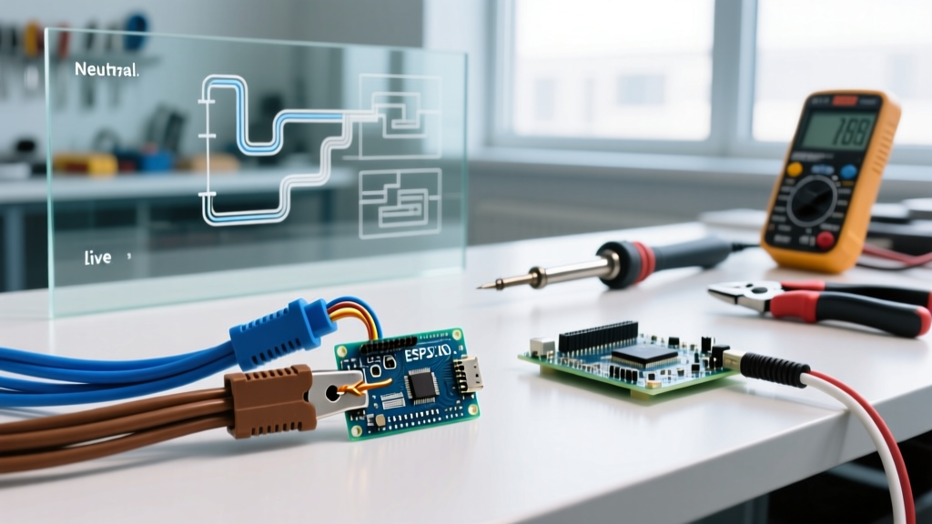

Understanding Electrical Wiring Blue Brown Configurations
When working on international appliances, solar inverters, or homes built to European, Australasian, and modern UK standards, encountering electrical wiring blue brown color schemes is inevitable. These colors are not arbitrary; they are strictly defined by the IEC 60445 standard to ensure global consistency and, more importantly, human safety. As we navigate the electrical landscape in 2026, the harmonization of global color codes has largely eliminated the chaos of regional variations, but it has also introduced severe risks for DIYers and electricians who are only familiar with North American (NEC) or legacy wiring standards.
Misidentifying a brown line conductor as a neutral, or assuming a blue wire is always safe to touch, can result in catastrophic equipment failure, arc flashes, or lethal electric shock. This comprehensive safety guide breaks down the physics, protocols, and professional termination techniques required when working with IEC harmonized cables.
The Global Shift: Decoding the IEC 60445 Standard
The transition to harmonized cable colors was one of the most significant shifts in modern electrical history. In the UK, for example, the transition from the old red/black system to the brown/blue system was mandated to align with mainland Europe, reducing fatal errors in cross-border trade and appliance manufacturing. According to the IET BS 7671 Wiring Regulations, strict adherence to these colors is legally required for all new installations and major rewires.
Color Code Comparison Matrix
Before opening any junction box or cutting into a cable sheath, you must understand how the IEC standard maps against other global systems. Confusing these is the leading cause of reversed polarity faults.
| Standard / Region | Line (Hot / Phase) | Neutral | Earth (Ground) |
|---|---|---|---|
| IEC 60445 (Current UK/EU/AUS) | Brown | Blue | Green/Yellow Stripe |
| Pre-2004 UK (Legacy) | Red | Black | Green |
| North America (NEC 2026) | Black (or Red) | White (or Grey) | Bare Copper / Green |
| IEC DC Systems (Solar/Off-Grid) | Brown (Positive) | Grey (Negative) | Green/Yellow Stripe |
The Lethal Risk of Reversed Polarity
The most common and dangerous failure mode when dealing with electrical wiring blue brown configurations is reversed polarity—specifically, swapping the brown (Line) and blue (Neutral) wires during termination. While an appliance with a simple resistive load (like a toaster or incandescent lamp) will still function perfectly if the wires are swapped, the safety implications are severe.
Why Swapping Brown and Blue is Dangerous
- Switched Neutrals: In a correctly wired IEC appliance, the internal switch or fuse is placed on the brown (Line) conductor. If brown and blue are reversed, the switch now breaks the neutral path. The appliance turns off, but the internal circuitry remains energized at 230V/240V relative to earth.
- Chassis Electrification: If a fault occurs inside the appliance while the neutral is switched off, the fault current cannot return via the neutral. Instead, the metal chassis can become fully energized. If the earth wire is compromised or missing, the next person to touch the appliance completes the circuit to ground, resulting in a lethal shock.
- Overcurrent Protection Failure: Fuses and single-pole circuit breakers are designed to interrupt the Line conductor. If placed on the neutral side due to reversed wiring, a short circuit may cause the fuse to blow, but the faulted circuit remains connected to the high-voltage supply, creating a persistent fire and shock hazard.
Expert Warning: Never assume a blue wire is safe to touch. In improperly wired circuits, multi-way switching setups, or older installations where cables were repurposed, a blue wire can be used as a switched line conductor or a traveler and carry full mains voltage. Always test before touching.
Step-by-Step Verification Protocol
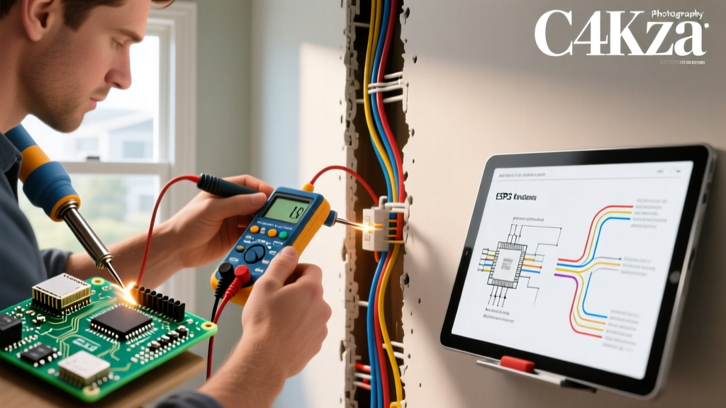
Visual inspection is never sufficient. Cable manufacturers occasionally make errors, and previous DIYers may have misused colors. The Health and Safety Executive (HSE) mandates rigorous testing protocols before any physical contact with conductors. Here is the professional verification sequence using a CAT III or CAT IV rated multimeter, such as the Fluke 117 True RMS Multimeter (retailing around $200 USD).
- Non-Contact Voltage Test (NCVT): Use a dual-range NCVT tester (e.g., Klein Tools NCVT-3, ~$35) to scan the outer sheath and individual wires. This confirms the presence of an active field without exposing you to live terminals.
- Line to Neutral Test (Brown to Blue): Set your multimeter to AC Voltage (V~). Insert the probes into the brown and blue conductors. You should read between 220V and 240V (depending on your local grid tolerance).
- Line to Earth Test (Brown to Green/Yellow): Move the black probe to the earth conductor. The reading should remain 220V-240V. If it reads significantly lower (e.g., 150V), you have a high-resistance ground fault or a floating neutral upstream.
- Neutral to Earth Test (Blue to Green/Yellow): This is the most critical safety check. The voltage between neutral and earth should be as close to 0V as possible (typically under 2V). If you read full mains voltage here, the neutral is disconnected upstream, and the blue wire is currently carrying the return load of the entire circuit. Touching it will result in a shock.
Professional Termination Techniques for IEC Cables
Harmonized brown and blue wires are frequently found in flexible appliance cords (H05VV-F or H07RN-F), which are almost always stranded. Terminating stranded wire directly into screw terminals without proper preparation is a leading cause of high-resistance hotspots and electrical fires.
The Ferrule Mandate
When connecting stranded brown and blue wires to screw-terminal blocks, DIN-rail contactors, or IEC appliance inlets, you must use bootlace ferrules. A ferrule is a small copper tube that is crimped onto the stripped end of the wire, converting it into a solid pin.
- Stripping: Use a precision wire stripper to remove exactly 8mm to 10mm of insulation, depending on the ferrule length. Do not nick the copper strands.
- Crimping: Use a dedicated ferrule crimper, such as the Knipex 97 53 14 (~$130). This tool ensures a square, gas-tight crimp that meets IEC 60352-2 standards. Pliers are unacceptable and will create a loose connection that arcs under load.
- Sizing: Match the ferrule color to the wire gauge. For standard 1.5mm² lighting circuits, use black ferrules. For 2.5mm² ring final circuits, use grey ferrules.
Using Lever Connectors for Mixed Wiring
When extending circuits or connecting solid-core house wiring to stranded brown/blue appliance pigtails, traditional twist-on wire nuts are highly discouraged. Instead, use WAGO 221 Series lever nuts (e.g., the WAGO 221-413 3-conductor lever nut, costing about $0.45 each). These connectors feature independent levers for each conductor, ensuring a gas-tight connection between dissimilar wire types (solid and stranded) without the risk of strand splay or copper fatigue from over-torquing screws.
Expert Troubleshooting FAQ
Can I use brown and blue wires for a 12V DC circuit?
While physically possible, it is a severe violation of IEC standards and a massive safety hazard. In IEC DC systems, brown is designated for the positive pole, but the negative pole should be grey, not blue. Blue is strictly reserved for AC neutral. Mixing AC and DC color codes in the same enclosure or conduit can lead a future technician to treat a high-current DC line as a harmless AC neutral, resulting in severe arc flash incidents.
What if the green/yellow earth wire is missing in an old appliance cord?
If you are rewiring a vintage appliance and the original cord only has brown and blue (or red and black) without an earth, the appliance is likely Class II (double-insulated). You must verify the presence of the double-square symbol on the appliance rating plate. If it is a Class I appliance (metal chassis requiring an earth), you must replace the cord with a modern 3-core H05VV-F cable featuring the green/yellow earth conductor. Never leave the earth pin unconnected on a 3-pin plug.
How do I handle a 3-phase system with brown, black, and grey wires?
In IEC 3-phase wiring (common in commercial settings and large solar arrays), the line conductors are Brown (L1), Black (L2), and Grey (L3). The blue wire remains the neutral, and green/yellow remains the earth. Never treat black or grey as neutral in an IEC environment. Always refer to the Fluke Measurement Categories guide to ensure your testing equipment is rated for the 400V phase-to-phase voltage present in these systems before taking measurements.
Final Safety Directives
Working with electrical wiring blue brown configurations demands respect for international standards and a methodical approach to testing. The harmonization of colors was designed to save lives, but it only works if the installer verifies the circuit's reality with a calibrated meter rather than relying on assumptions. Invest in high-quality CAT III/IV testing equipment, use proper ferrule termination methods, and always isolate the circuit at the main distribution board before beginning any physical work.