
The Complexity of Modern Wiring Harness Diagnostics
Electrical wiring harnesses are the central nervous system of any complex machine, from custom automotive builds and marine vessels to industrial automation cabinets. As of 2026, the shift toward 48V mild-hybrid architectures in automotive and 800V platforms in EV systems means that harness faults are no longer just about blown fuses or dead lights. A single compromised shielded twisted pair can crash an entire CAN-FD network, while a micro-abrasion in a high-voltage XLPE (cross-linked polyethylene) cable can trigger catastrophic isolation faults.
Troubleshooting electrical wiring harnesses requires moving beyond simple test-light probes. It demands a systematic approach to isolating opens, shorts, parasitic draws, and high-resistance faults without causing secondary damage to sensitive ECUs (Electronic Control Units). This guide provides a field-tested, professional-grade diagnostic protocol for identifying and resolving harness anomalies.
Essential Diagnostic Arsenal
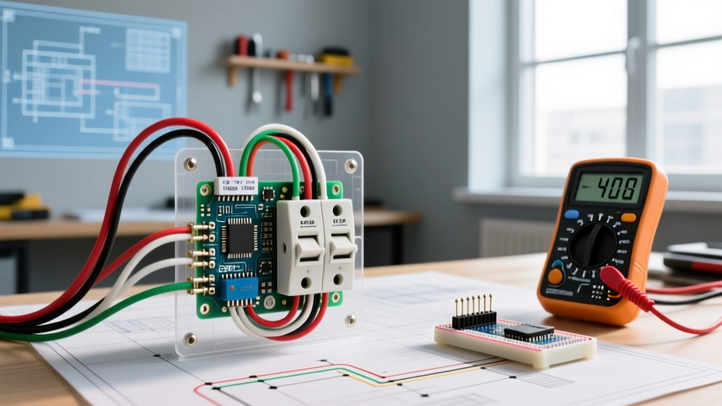
Before dissecting a loom, ensure your test equipment is calibrated and appropriate for the harness class. Relying on a basic $20 multimeter will miss intermittent high-resistance faults and dielectric breakdowns.
- Digital Multimeter (DMM): A true-RMS meter with milliohm resolution, such as the Fluke 87V (approx. $450), is mandatory for accurate voltage drop and continuity testing.
- Insulation Resistance Tester (Megger): For industrial or high-voltage harnesses, a Fluke 1587 FC (retailing around $650 in 2026) is essential to test dielectric integrity at 250V, 500V, or 1000V DC without damaging standard low-voltage wire insulation.
- Automotive Breakout Boxes: Tools like the OTC 5645A allow you to back-probe ECU connectors safely, preventing terminal 'mushrooming' that occurs when forcing standard probes into delicate Molex MX150 or TE Connectivity Superseal cavities.
- Tone Generator and Inductive Amplifier: Crucial for tracing unmarked wires inside dense, heavily taped bundles where visual tracing is impossible.
The 5 Most Common Harness Failure Modes
Understanding how and why electrical wiring harnesses fail allows you to target your diagnostic efforts. The following matrix outlines the most frequent failure modes encountered in the field, their root causes, and their electrical signatures.
| Failure Mode | Primary Root Cause | Diagnostic Signature | Typical Location |
|---|---|---|---|
| Terminal Push-Out | Improper crimping or missing connector locking tang (TPA/CPA). | Intermittent open circuit; resistance spikes when wire is wiggled. | ECU connectors, bulkhead pass-throughs. |
| Chafing / Abrasion | Insufficient loom securing; vibration against sharp metal edges. | Short to ground (0 ohms to chassis); blown fuses; localized heat. | Firewall grommets, steering column drops, hinge pillars. |
| Galvanic Corrosion | Capillary wicking of moisture due to missing drip loops or failed seals. | High resistance (5 to 50 ohms) across a continuous wire; voltage drop. | Weather-pack seals, exterior lighting pigtails, marine bilge areas. |
| Dielectric Breakdown | Thermal degradation of PVC or chemical exposure melting insulation. | Intermittent short between adjacent wires under high load/voltage. | Engine bay exhaust proximity, industrial motor junction boxes. |
| Strand Fatigue | Repeated flexing in moving assemblies (e.g., robotic arms, doors). | Open circuit that only appears in specific physical positions. | Door jamb boots, robotic dress packs, trailer hitch loops. |
Step-by-Step Troubleshooting Protocol
When a harness fault is suspected, follow this strict sequence to isolate the issue efficiently. This methodology aligns with the troubleshooting frameworks recommended in the IPC/WHMA-A-620 standard for cable and wire harness assemblies.
Phase 1: Visual and Tactile Inspection
Never skip the physical inspection. Roughly 40% of harness faults are visible. Run your hands along the length of the loom, feeling for:
- Hard Spots: A stiff section inside a flexible loom often indicates melted insulation or a corroded, crystallized splice.
- Grommet Seating: Ensure rubber bulkhead grommets are fully seated. A partially ejected grommet allows water ingress and wire chafing against the sheet metal.
- Drip Loops: Verify that connectors mounted vertically have a drip loop (a U-shaped bend in the wire before the connector) to prevent capillary action from drawing water into the terminal cavity.
Phase 2: Point-to-Point Continuity and Voltage Drop
If the visual inspection yields nothing, move to electrical testing. Disconnect both ends of the suspect harness segment to prevent back-feeding through solid-state components.
- Continuity Check: Measure resistance end-to-end. A healthy 18 AWG copper wire over a 10-foot run should read less than 0.5 ohms. If you read 2 to 10 ohms, you have strand corrosion or a failing crimp.
- Voltage Drop Testing (Live Circuit): With the circuit energized, place your DMM leads on either end of the wire (positive to positive, negative to negative). A voltage drop exceeding 0.1V per connection or 0.2V for the entire wire length indicates excessive resistance under load.
Phase 3: Insulation Resistance (Megger Testing)
For shorts that only appear when the system is under full voltage, or for testing high-voltage EV harnesses, use an insulation resistance tester. According to Fluke's insulation testing guidelines, applying a DC test voltage (e.g., 500V for 600V-rated wire) stresses the dielectric. A healthy harness will read in the hundreds of Megohms (MΩ). A reading below 1 MΩ indicates compromised insulation that will eventually arc or short out, requiring immediate harness replacement or localized excision.
Edge Case: Diagnosing High-Speed Data Networks
Expert Warning: Never use a Megger or standard continuity tester on active CAN bus, LIN, or Ethernet lines without isolating the transceivers. The high voltage or test current will instantly destroy the communication ICs.
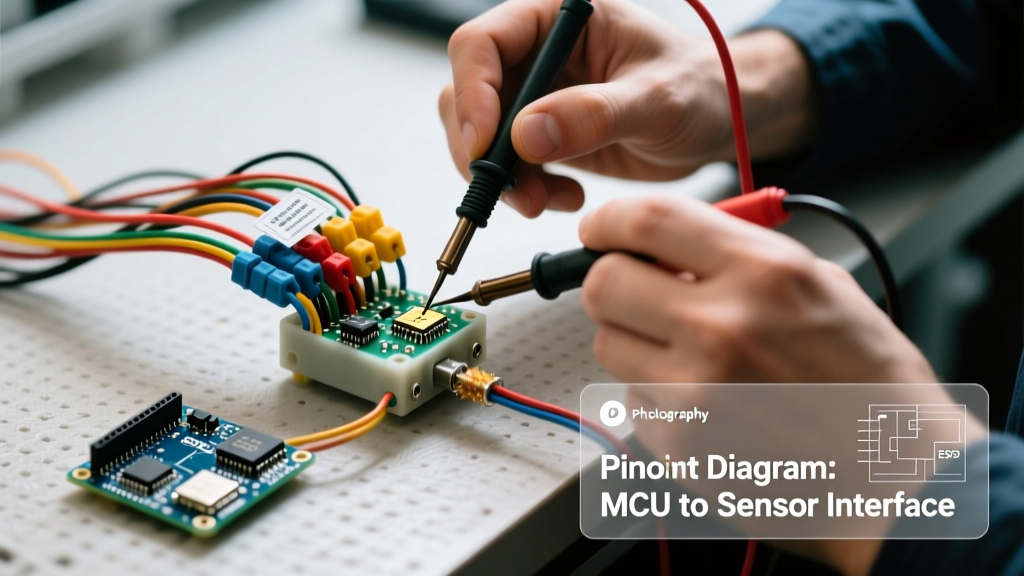
Modern electrical wiring harnesses heavily feature shielded twisted pairs for data. When troubleshooting a CAN-FD or standard High-Speed CAN network, the primary metric is the termination resistance. The network requires exactly two 120-ohm resistors at the extreme ends of the bus. When measured across the CAN_H and CAN_L pins at the OBD-II port or central gateway with the battery disconnected, your DMM should read exactly 60 ohms (the parallel equivalent of two 120-ohm resistors).
- Reading 120 Ohms: One termination resistor is missing, or there is an open circuit in the harness splitting the network in half.
- Reading 40 Ohms or Lower: An extra termination resistor has been erroneously added, or the CAN_H and CAN_L wires are shorted together.
- Reading Infinite (OL): Both resistors are missing, or the harness is completely severed.
For signal integrity issues (e.g., CAN bus dropping offline under high EMI), use an automotive oscilloscope like the PicoScope 4225D to check for symmetrical square waves. Asymmetry indicates a short to ground on one of the twisted pair legs or a compromised braided shield.
Repair vs. Replace Decision Matrix
Once the fault is isolated, the final step is determining whether to repair the electrical wiring harness or replace the entire assembly. Industry best practices, including those outlined by NASA's workmanship standards for critical wiring, dictate strict limits on splicing.
When to Repair
Localized damage (e.g., a single chafed wire near a connector) can be repaired using MIL-SPEC solder sleeves (such as Raychem SO96 series) or ultrasonic welders. The repair must maintain the original wire's flexibility, current-carrying capacity, and environmental sealing. Always use adhesive-lined, dual-wall heat shrink tubing (like 3M FP-301 with a 3:1 shrink ratio) to ensure a waterproof seal. If the harness uses a shielded cable, the shield braid must be meticulously spliced and wrapped with copper foil tape before applying the outer jacket.
When to Replace
Complete harness replacement is mandatory under the following conditions:
- Capillary Wicking: If corrosion is found more than 3 inches inside the wire insulation, the copper strands have wicked moisture deep into the loom. Cutting out the visible corrosion will not solve the issue; the entire branch must be replaced.
- Thermal Cascading: If a short circuit has melted the outer PVC loom covering and fused multiple adjacent wires together, the dielectric integrity of the entire bundle is suspect.
- High-Voltage (Orange) Cables: In EV and hybrid platforms, OEMs strictly prohibit splicing high-voltage interlock loop (HVIL) or main traction cables due to the severe arc-flash and fire risks. These must always be replaced as complete assemblies.
Final Verification
After any repair or replacement, perform a full system load test. Do not rely solely on a static multimeter reading. Activate all circuits on the repaired harness branch simultaneously (e.g., turn on headlights, HVAC blower, and wipers) and monitor the voltage drop across the main power and ground feeds. A successful troubleshooting session ends not just when the fault is cleared, but when the harness is verified to handle peak operational loads without thermal degradation or signal loss.