
Strategic Planning for Two-Speed Motor Installations
Designing and executing a reliable control circuit for a two-speed motor requires more than just connecting power leads. Whether you are upgrading a commercial HVAC air handler, a pool filtration system, or an industrial conveyor, understanding the exact wiring diagram for two speed motor configurations is critical to preventing contactor welding, minimizing mechanical transients, and ensuring compliance with the National Electrical Code (NEC). This installation planning guide breaks down the electrical topology, component sizing, and control logic required for a robust 2026-compliant motor starter setup.
Identifying Your Motor Topology: Dahlander vs. Separate Winding
Before pulling a single foot of THHN wire, you must read the motor nameplate to determine the internal winding topology. Two-speed motors generally fall into two categories:
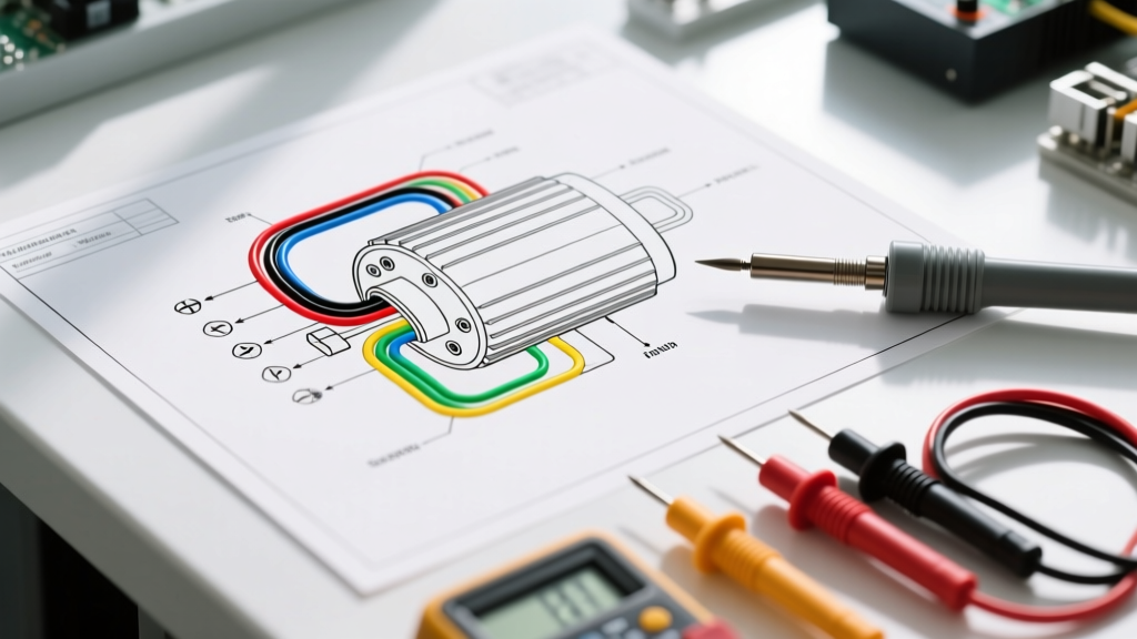
- Dahlander (Pole-Changing) Motors: Utilize a single tapped winding. By altering the connection from Series Wye (Low Speed) to Parallel Wye / YY (High Speed), the number of magnetic poles is halved, doubling the RPM. These typically feature 6 terminals (U1, V1, W1, U2, V2, W2) and are common in variable-torque applications like centrifugal pumps and fans.
- Separate Winding Motors: Contain two completely independent stator windings (e.g., 4-pole and 6-pole). These often have 9 or 12 leads and are used when specific torque profiles or non-standard speed ratios are required.
Expert Insight: The vast majority of modern commercial HVAC and pool pump applications (such as the Regal Rexnord Century Centurion series) utilize the Variable Torque Dahlander configuration. The wiring diagram logic below assumes a 6-lead Dahlander Wye/YY setup, which requires three contactors: one for Low Speed, one for High Speed line power, and a third for the YY parallel bridging.
Pre-Installation Sizing & Bill of Materials (BOM)
Sizing your motor control components incorrectly is the leading cause of premature failure. Per NFPA 70 (NEC) Article 430, overloads and conductors must be sized based on the specific Full Load Amps (FLA) of the speed being utilized. Because a Dahlander motor has two distinct FLA ratings, you must install two separate thermal overload relays in the power circuit, or utilize a modern electronic overload with dual-setting digital inputs.
Below is a sample BOM and estimated 2026 pricing for a 5 HP, 230V, 3-Phase Variable Torque Dahlander motor (High Speed FLA: 14.0A | Low Speed FLA: 5.5A) using industry-standard Schneider Electric TeSys components:
| Component Description | Model / Part Number | Qty | Est. Unit Price |
|---|---|---|---|
| Main Disconnect Switch (NEMA 3R) | TeSys Vario V2 (32A) | 1 | $115.00 |
| Low Speed Contactor (Category AC-3) | TeSys LC1D09 (9A / 230V) | 1 | $58.00 |
| High Speed Line Contactor | TeSys LC1D18 (18A / 230V) | 1 | $72.00 |
| High Speed Bridging Contactor (YY) | TeSys LC1D18 (18A / 230V) | 1 | $72.00 |
| Mechanical Interlock Block | LAD9R1V (Reversing/Interlock) | 1 | $24.00 |
| Thermal Overload Relay (High Speed) | LRD21 (12A - 18A) | 1 | $65.00 |
| Thermal Overload Relay (Low Speed) | LRD12 (5.5A - 8A) | 1 | $65.00 |
| Control Circuit Transformer | 90-T50F3 (50VA, 240/24VAC) | 1 | $88.00 |
Control Circuit Logic and Mandatory Interlocking
The most critical aspect of any wiring diagram for two speed motor setups is the control circuit interlocking. If the Low Speed contactor and the High Speed bridging contactor close simultaneously, you will create a catastrophic phase-to-phase dead short through the motor windings.
Hardwired Interlocking Requirements
- Electrical Interlocking: Wire the Normally Closed (NC) auxiliary contact of the Low Speed contactor in series with the coils of both High Speed contactors. Conversely, wire the NC auxiliaries of the High Speed contactors in series with the Low Speed coil.
- Mechanical Interlocking: Always install a mechanical interlock block (e.g., Schneider LAD9R1V) between the Low Speed and High Speed Line contactors. Electrical interlocks can fail due to welded contacts; mechanical interlocks provide a physical barrier preventing simultaneous closure.
- Transition Timing (Open Transition): When switching from High to Low speed, the motor acts as a generator due to inertia. Reclosing the Low Speed contactor while back-EMF is still present can cause massive current spikes and mechanical shock to the pump impeller. Incorporate a programmable logic relay or a pneumatic off-delay timer to enforce a 0.5 to 1.5-second dead time between dropping the High Speed contactors and engaging the Low Speed contactor.
NEC Compliance: Conductor Sizing and Routing
According to the Electrical Apparatus Service Association (EASA) and NEC Article 430.22, motor branch circuit conductors must have an ampacity of not less than 125% of the motor's full-load current rating. For a multi-speed motor, you must calculate based on the highest FLA rating on the nameplate.
Calculation Example (5HP, 230V, High Speed FLA = 14.0A):
14.0A × 1.25 = 17.5 Amperes.
While 12 AWG THHN (rated 25A at 75°C) technically meets the minimum ampacity requirement, standard industry practice in 2026 dictates using 10 AWG THHN for all power leads to the motor. This provides superior mechanical strength at the terminal lugs, mitigates voltage drop over longer conduit runs, and accommodates the high inrush currents (LRA) inherent to across-the-line starting. Furthermore, NEC 430.33 requires that the secondary winding taps (the U2, V2, W2 leads used for bridging in YY) be treated as motor circuit conductors and must be routed in the same raceway as the primary power leads to prevent inductive heating and EMI issues.
Common Failure Modes and Edge Cases
Even with a perfect wiring diagram, field conditions introduce variables that can destroy a two-speed motor setup. Watch for these specific failure modes:
- Contactor Welding on Speed Reversal: If the transition timer is set too short (e.g., < 0.2 seconds), the out-of-phase reclosing current can exceed the contactor's breaking capacity, welding the contacts shut. Always verify the decay of back-EMF using an oscilloscope during commissioning if the driven load has high inertia.
- Single-Phasing on the Bridging Contactor: If the YY bridging contactor fails to close one pole, the motor will attempt to run on an open-delta equivalent, resulting in severe unbalanced currents. Standard bi-metallic overloads may not trip fast enough to prevent stator burnout. Upgrade to solid-state or electronic overloads (like the TeSys Giga series) with built-in phase-loss and phase-imbalance detection.
- Low-Speed Overload Nuisance Tripping: If the Low Speed overload relay is not properly isolated from the High Speed circuit during the transition phase, the thermal memory of the bi-metal strip may cause a nuisance trip upon starting. Ensure the control logic completely isolates the inactive overload relay from the main power path.
Final Commissioning Checklist
Before energizing the main disconnect, verify the following:
1. Megger test all six motor leads to ground (minimum 2 Megohms at 500VDC).
2. Verify phase rotation (L1-U1, L2-V1, L3-W1) using a phase rotation meter. Incorrect rotation on a Dahlander motor will cause it to run in reverse on one speed and forward on the other, potentially destroying centrifugal pump seals.
3. Manually actuate each contactor with an insulated tool to confirm mechanical interlock binding.
4. Set the High Speed overload dial exactly to the nameplate High FLA, and the Low Speed dial to the Low FLA. Do not average them.