
Mastering the Electrical Schematic of Your Zero-Turn Mower
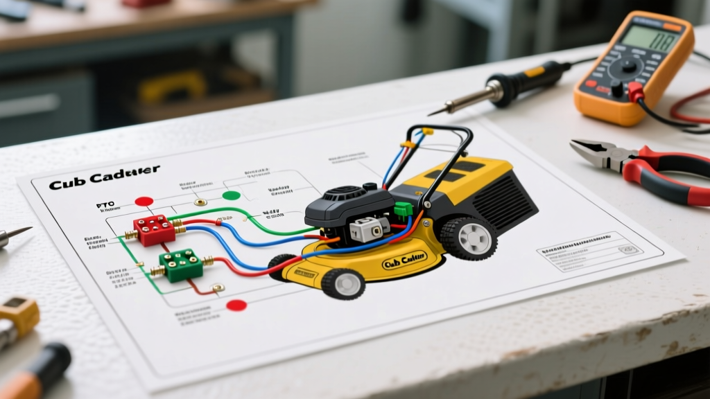
Treating a commercial or residential zero-turn mower like a simple mechanical device is a mistake. Modern machines, such as the Cub Cadet Ultima ZT1 50 or the Z-Force S46, are essentially complex outdoor appliances governed by intricate 12V DC electrical networks. When your mower fails to crank, the PTO clutch refuses to engage, or the battery drains overnight, guessing at the fix will only cost you time and money. Learning how to interpret a wiring diagram for Cub Cadet zero turn models is the most critical skill for any DIY equipment technician.
In this comprehensive appliance wiring tutorial, we will deconstruct the electrical architecture of Cub Cadet zero-turn mowers. We will cover the safety interlock logic, PTO clutch power delivery, and starter solenoid circuits, providing exact multimeter readings, wire gauge specifications, and 2026 OEM pricing data to guide your repairs.
⚠️ CRITICAL SAFETY WARNING: Before probing any circuit or consulting your schematic, always disconnect the negative (-) battery terminal. Zero-turn mowers utilize high-amperage 12V systems capable of delivering 300+ cold cranking amps (CCA). A short circuit across an unfused main power wire can instantly weld metal tools and cause severe electrical fires.
The Three Core Circuits of a Cub Cadet Zero Turn
When you pull up the official Cub Cadet wiring schematics, the harness can look like a bowl of spaghetti. To simplify your troubleshooting, mentally divide the wiring diagram into three distinct sub-systems:
- The Cranking Circuit: Handles high-current loads (150A–300A) from the battery to the starter solenoid and starter motor. This circuit uses heavy 6 AWG or 4 AWG battery cables.
- The Charging Circuit: Originates at the engine stator (under the flywheel of your Kohler or Kawasaki engine), passes through a voltage regulator/rectifier, and replenishes the 12V battery while mowing.
- The Accessory & Logic Circuit: A low-current (1A–15A) network that powers the ignition switch, safety interlock module, hour meter, and the PTO clutch relay.
Decoding the Safety Interlock System
The most common reason a Cub Cadet zero-turn fails to start or shuts off unexpectedly is a fault in the safety interlock system. The wiring diagram uses a series of normally-open (NO) and normally-closed (NC) switches wired in series or fed into a solid-state interlock module to ensure the operator is present and the machine is in a safe state before cranking or engaging the blades.
Interlock Logic Matrix
Use this table to understand the required switch states for specific operations. If your mower fails a test, trace the specific circuit path on your schematic to find the open switch.
| Operation | Seat Switch | PTO Switch | Lap Bars / Brakes | Ignition State |
|---|---|---|---|---|
| Engine Cranking | Occupied (Closed) | DISENGAGED (Open) | Outward / Locked (Closed) | Start Position |
| Normal Mowing | Occupied (Closed) | ENGAGED (Closed) | Inward / Unlocked (Closed) | Run Position |
| Reverse Mowing (PTO Active) | Occupied (Closed) | ENGAGED (Closed) | Reverse Trigger Pulled | Run Position |
| Operator Dismount (Engine Dies) | Unoccupied (Open) | Any State | Outward / Unlocked | Run Position |
Note: On newer 2025-2026 Cub Cadet models, these discrete switches often feed into a centralized Body Control Module (BCM) rather than using direct series-wiring. Always verify if your schematic shows a BCM logic gate or direct relay grounding.
Deep Dive: Troubleshooting the PTO Clutch Circuit
The Power Take-Off (PTO) clutch is an electromagnetic appliance that engages the mower deck belt. It draws a massive amount of current for a 12V accessory—typically between 4 and 6 amps continuously. Because of this high draw, the PTO circuit is a frequent point of failure.
Step-by-Step PTO Diagnostic Flow
If your wiring diagram shows power leaving the ignition switch, passing through the PTO toggle switch, and hitting a relay, follow these steps to isolate the fault:
- Step 1: Check the Inline Fuse. Most Cub Cadet ZTs use a 30A or 40A automotive blade fuse located near the battery or starter solenoid. A blown fuse indicates a short to ground, usually caused by a melted wire harness rubbing against the steering damper or engine block.
- Step 2: Test the Relay. The wiring diagram will show a standard 4-pin or 5-pin ISO relay. With the key in the 'Run' position and the PTO switch pulled, use a multimeter to check for 12V at the relay's trigger pin (usually pin 86). If you have 12V on the trigger and a solid ground on pin 85, but no 12V output at pin 87, the relay contacts are burned. Replace the relay (OEM cost: ~$18; aftermarket: ~$9).
- Step 3: Measure Clutch Coil Resistance. Disconnect the wiring harness plug at the PTO clutch itself. Set your multimeter to Ohms (Ω). Place the probes on the two clutch terminals. According to Kohler and Warner Electric engineering specifications, a healthy 12V PTO clutch should read between 2.5 and 4.5 ohms at 75°F.
- If it reads 0.0 ohms, the internal coil is shorted (this is what blew your 30A fuse).
- If it reads OL (Infinite), the coil wire is broken internally.
- Step 4: Inspect the Air Gap. Even with perfect wiring, a PTO clutch will slip or overheat if the physical air gap is incorrect. Use a feeler gauge to measure the gap between the rotor and the armature. It must be precisely 0.010 to 0.015 inches. If it exceeds 0.025 inches, adjust the three perimeter nuts and springs before condemning the electrical system.
Wire Gauge and Routing Specifications (SAE Standards)
When repairing a damaged harness on your Cub Cadet, never use standard household copper wire (THHN/THWN). Outdoor power equipment is subjected to extreme vibration, moisture, and engine bay temperatures exceeding 200°F. You must use automotive primary wire that meets SAE J1128 standards, specifically GXL (cross-linked polyethylene) insulation, which resists melting when routed near the exhaust manifold.
| Wire Gauge (AWG) | SAE J1128 Ampacity | Typical Application on Cub Cadet ZT | Insulation Type Required |
|---|---|---|---|
| 4 AWG | 120A - 150A | Battery to Starter Solenoid Main Feed | SGT / Welding Cable |
| 10 AWG | 30A - 40A | PTO Clutch Power Feed, Alternator Output | GXL (High Temp) |
| 12 AWG | 20A - 25A | Headlights, 12V Accessory Port, Charging Relay | GXL or SXL |
| 16 AWG | 10A | Ignition Switch Logic, Safety Interlock Switches | PVC Primary (Standard) |
Common Edge Cases and Hidden Failure Modes
Even with a perfect wiring diagram, some issues defy basic continuity testing. As an experienced technician, you must look out for these specific edge cases common to the Cub Cadet zero-turn lineup:
1. The 'Voltage Drop' Phantom
Your multimeter shows 12V at the PTO clutch connector, but the clutch won't engage. This is a classic voltage drop issue caused by internal corrosion inside the wire or a failing crimp terminal. The wire has enough continuity to show 12V with no load (multimeter), but the resistance is too high to pass the 5 amps required to magnetize the clutch coil. The Fix: Perform a voltage drop test while the circuit is under load. Place your multimeter probes on the battery positive and the clutch positive terminal while the PTO is switched on. A drop of more than 0.5V indicates a bad wire or connection.
2. Corroded Chassis Grounds
Cub Cadet relies heavily on the steel frame for ground returns to save on copper wire costs. The starter solenoid, voltage regulator, and interlock modules often ground directly to the chassis. If you live in a region that uses road salt or if you frequently pressure-wash your mower deck, these ground points will oxidize. Always scrape the paint and rust down to bare, shiny metal, apply a star washer for a mechanical bite, and coat the terminal in dielectric grease.
3. Stator Diode Backfeed
If your mower battery is fully charged but dies after sitting for 48 hours, and the wiring diagram shows a 3-wire stator plug going into the voltage regulator, suspect a failed internal diode in the regulator. The diode is meant to allow current to flow to the battery, but when it fails short, it allows 12V battery current to backfeed into the stator coils, draining the battery and cooking the stator windings. As of 2026, an OEM Kohler voltage regulator costs between $65 and $90. Always test the stator AC output (should be 28V-35V AC at 3600 RPM) before replacing the regulator to ensure you don't blow the new part.
Final Thoughts on Harness Maintenance
Understanding the wiring diagram for your Cub Cadet zero turn mower transforms you from a parts-swapper into a true diagnostician. When executing repairs, abandon cheap electrical tape and twist-on wire nuts. Invest in a marine-grade heat shrink kit with adhesive-lined tubing and a proper ratcheting wire crimper. By respecting the SAE wire standards and rigorously testing the safety interlock logic, your zero-turn mower will deliver reliable, commercial-grade performance for thousands of operating hours.