
The Master Wiring Diagram for Car Amp: System Flow
Installing a high-output car audio system requires more than just connecting positive and negative terminals. Whether you are running a compact Class D mono block like the Rockford Fosgate Prime R2-500X1 or a massive 3000W SPL amplifier, understanding the complete wiring diagram for car amp integration is critical. A flawed installation leads to voltage drop, alternator whine, or catastrophic electrical fires. This 2026 step-by-step walkthrough breaks down the exact routing, material selection, and termination procedures used by professional mobile electronics technicians.
Before cutting a single wire, visualize the complete DC power and signal flow. The master wiring diagram for a standard single-amplifier car audio system follows this strict path:
- Power Flow: Battery Positive (+) → Inline Fuse (within 18 inches) → Firewall Grommet → Amplifier B+ Terminal.
- Ground Flow: Amplifier GND Terminal → Bare Metal Chassis Point → Vehicle Battery Negative (-).
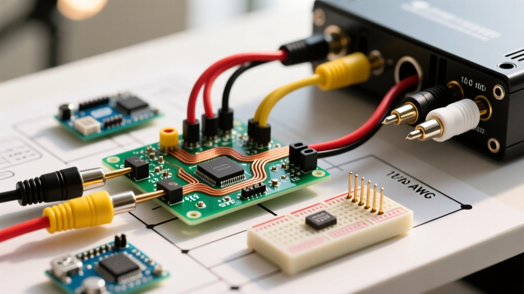
- Signal Flow: Head Unit RCA Preouts → Shielded RCA Cables → Amplifier Input.
- Trigger Flow: Head Unit Remote Turn-On (Blue/White) → Amplifier REM Terminal.
Pre-Install Hardware & Wire Sizing Matrix
The most common mistake in mobile electronics is undersizing the power wire or falling for deceptive marketing on budget wire kits. In 2026, the market is flooded with Copper-Clad Aluminum (CCA) wire. While a 20-foot CCA kit might cost around $35, it exhibits up to 30% higher resistance than true Oxygen-Free Copper (OFC), which costs closer to $85. For high-current draws, OFC is non-negotiable to prevent voltage drop and overheating.
| Wire Gauge (AWG) | Max Current (Amps) | Recommended Fuse | Est. 2026 OFC Cost (20ft) |
|---|---|---|---|
| 8 AWG | Up to 50A | 40A - 50A ATC/ANL | $45 - $60 |
| 4 AWG | Up to 85A | 80A ANL | $75 - $95 |
| 2 AWG | Up to 130A | 120A ANL | $110 - $140 |
| 1/0 AWG | Up to 185A | 150A - 200A ANL | $160 - $210 |
Expert Note on Fuses: Never use AGU (glass tube) fuses for systems drawing over 60A. At high currents, the internal element can melt and fuse the glass without breaking the circuit. Always use ANL or Class-T fuses for high-power car amp wiring diagrams.
Step-by-Step Wiring Walkthrough
Phase 1: Power Wire Routing & Firewall Penetration
Disconnect the negative terminal of your vehicle's battery before beginning. Route the main OFC power wire from the battery to the amplifier location (usually the trunk or under a seat). You must pass through the vehicle's firewall using an existing rubber grommet. Never drill a new hole near the steering column or brake lines.
Pierce the rubber grommet with a small awl, push the wire through, and seal the puncture with high-temp silicone. Secure the power wire with zip ties every 12 inches, ensuring it stays at least 2 inches away from exhaust components and moving suspension parts. Terminate the battery end with a closed-loop ring terminal, crimped with a hex-crimp tool and sealed with adhesive-lined heat shrink.
Phase 2: The Inline Fuse (Critical Safety Step)
The inline fuse is the most vital safety component in your wiring diagram. It must be installed on the main power wire within 18 inches of the battery positive terminal. If a short occurs between the battery and the amplifier, this fuse prevents the wire from turning into a blowtorch. Install the fuse holder, but leave the fuse out until the very end of the installation.
Phase 3: Grounding the Amplifier (The Zero-Tolerance Rule)
Poor grounding is responsible for 90% of all car audio noise and failure issues. The amplifier's ground wire should be kept as short as possible (under 3 feet).
- Locate a solid, structural bolt on the vehicle chassis (avoid seatbelt anchors or thin sheet metal).
- Remove the bolt and use 80-grit sandpaper to strip away all paint, primer, and rust down to bare, shiny metal.
- Crimp a heavy-duty ring terminal onto your ground wire.
- Bolt the terminal directly to the bare metal. Tighten with a torque wrench to factory specifications.
- Apply a coating of dielectric grease over the connection to prevent future oxidation and rust.
Phase 4: Signal (RCA) & Remote Turn-On Routing
To prevent electromagnetic interference (EMI) and alternator whine, RCA signal cables must never run parallel to the main power wire. Route your power wire down the driver's side of the vehicle, and route your RCA cables and remote turn-on wire down the passenger side.
For the remote turn-on wire, connect it to the head unit's Blue/White wire (Amplifier Turn-On). Do not connect it to the solid Blue wire (Power Antenna), as the solid blue wire drops to 0V when you switch from the radio to Bluetooth or CD, which will cause your amplifier to shut off mid-playback.
Phase 5: Speaker Wire & Impedance Matching
When wiring subwoofers to the amplifier's output terminals, ensure your final impedance matches the amplifier's stable rating. For example, if you have a mono amp stable at 2 ohms, and two dual 4-ohm voice coil (DVC) subwoofers, you must wire the voice coils in series (to get 8 ohms per sub) and then wire the two subwoofers in parallel to achieve a final 4-ohm load. Wiring them incorrectly to a 1-ohm load will immediately trigger the amplifier's thermal protection circuit.
Troubleshooting Matrix: Diagnosing Post-Install Failures
Even with a perfect wiring diagram for your car amp, issues can arise. Use this diagnostic matrix to isolate faults without guessing.
| Symptom | Root Cause | Diagnostic Fix |
|---|---|---|
| Alternator Whine (RPM pitch) | Ground loop or RCA proximity to power | Verify head unit and amp share a common ground potential. Ensure RCA and power wires cross at 90-degree angles, never parallel. |
| Amp goes into Protect Mode | Impedance mismatch or shorted speaker wire | Disconnect all speaker wires. If the amp powers on normally, the issue is a pinched speaker wire or a blown subwoofer voice coil. |
| No Turn-On (Amp stays dead) | Remote wire voltage drop or blown inline fuse | Test the blue/white remote wire with a multimeter. It must read >11V when the head unit is on. Check the main ANL fuse. |
| Bass drops at high volume | Voltage drop / undersized wire | Measure voltage at the amp B+ and GND terminals while playing bass. If it drops below 11.5V, upgrade to a larger AWG wire or add a secondary battery. |
Final System Testing & Gain Matching
Once all connections are secure, insert the main ANL fuse and reconnect the vehicle's battery negative terminal. Turn on the head unit. The amplifier's power LED should illuminate green.
Before setting the gain, play a 50Hz test tone at 75% volume. Use an oscilloscope or a digital multimeter (set to AC Volts) connected to the amplifier's speaker outputs. Calculate the target AC voltage using the formula: Voltage = Square Root of (Watts × Ohms). Adjust the gain knob until the multimeter reads the target voltage, ensuring you are matching the amplifier's output to your subwoofers' RMS rating without introducing clipping. Clipping sends squared DC voltage to your speakers, which will burn the voice coils in a matter of minutes.
Authoritative References & Further Reading
For further reference on mobile electronics standards, advanced DSP gain matching, and safety protocols, consult the following industry authorities:
- Crutchfield Amplifier Installation Guide - Comprehensive vehicle-specific wiring tutorials and firewall routing techniques.
- Rockford Fosgate Technical Support - Official tech bulletins on Class D amplifier efficiency and impedance matrices.
- JL Audio Support Documentation - Advanced documentation on clean-signal integration and OEM audio system bypass wiring.