
The Critical Importance of Safe Amp Meter Wiring
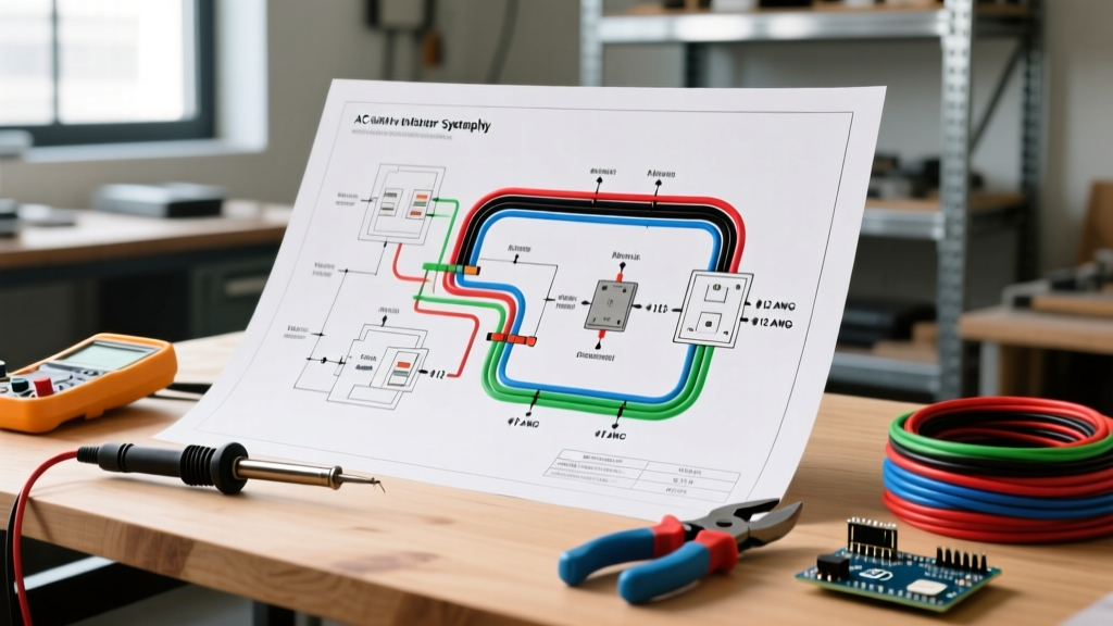
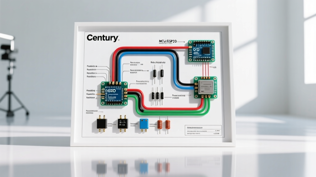
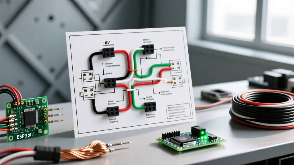
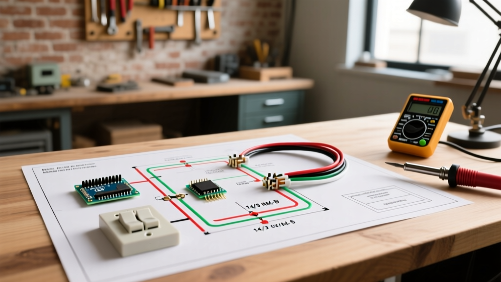
When searching for a reliable wiring diagram for amp meter installations, electrical professionals and advanced DIYers must prioritize safety and code compliance above all else. Ammeters are essential for load balancing, monitoring continuous draws from modern Level 3 EV chargers, and preventing thermal overloads in residential and commercial panels. However, an incorrect wiring configuration can lead to catastrophic arc flashes, destroyed equipment, or lethal secondary voltages.
As of 2026, with the proliferation of high-draw solar inverters and bidirectional charging systems, precise National Electrical Code (NEC) compliant metering is non-negotiable. This guide breaks down the two primary methods for measuring high current—inline shunts and Current Transformers (CTs)—providing exact wiring protocols, component specifications, and critical safety warnings based on NFPA 70 (NEC) standards.
Core Safety Principles & NEC Code Compliance
Before touching a single wire, you must understand that metering circuits must be treated with the same respect as the primary conductors they monitor. The NEC outlines strict rules for instrument wiring, particularly regarding isolation, grounding, and overcurrent protection.
- NEC Article 250 (Grounding and Bonding): Instrument transformer secondary circuits must be grounded to prevent static buildup and floating voltages that can compromise insulation.
- NEC Article 300.3(C) (Conductors of Different Systems): Low-voltage metering wires must be physically separated from high-voltage primary conductors unless separated by a grounded metal barrier or enclosed in approved raceways.
- Continuous Load Derating: Under NEC Article 100 definitions, any load expected to run for 3 hours or more (like HVAC or EV chargers) is continuous. Shunts and CTs must be sized at 125% of the maximum continuous current to prevent thermal drift and inaccurate readings.
Method 1: Inline Shunt Wiring Diagram & Safety Protocol
Inline shunts are precision resistors that output a millivolt (mV) signal proportional to the current passing through them. The industry standard for DC and low-voltage AC analog/digital panel meters is a 50mV drop at full-scale deflection.
Recommended Components & Pricing
- Shunt: Moduline or Deltec 100A 50mV DC/AC Shunt (Approx. $35 - $50). These feature manganese-nickel alloy resistive elements for high thermal stability.
- Meter: Digital panel meter with 50mV input scaling (e.g., Bayite DC 6.5-100V 50A, approx. $22).
- Wiring: 18 AWG Shielded Twisted Pair (STP) for the mV signal to reject electromagnetic interference (EMI).
Step-by-Step Wiring Procedure
- Interrupt the Primary Circuit: Never install a shunt on a live busbar. De-energize, lockout/tagout (LOTO), and verify zero voltage.
- Mount the Shunt: Secure the shunt to a non-conductive, heat-resistant surface. Ensure adequate airflow; a 100A shunt dissipating 5 watts of heat requires ventilation to prevent resistance drift.
- Connect Primary Conductors: Attach the main power cables to the outer, heavy-duty current terminals of the shunt. Torque to manufacturer specifications (typically 40-50 in-lbs for 1/4" hardware).
- The Kelvin Connection (Crucial Step): Wire the meter's sense leads to the inner, smaller potential terminals.
Expert Warning: A classic journeyman mistake is wiring the meter to the outer current terminals. The contact resistance of the heavy lugs will add to the shunt's resistance, causing massive reading errors and localized heating. Always use the inner Kelvin terminals for the mV signal.
- Fuse the Meter Leads: Install a 0.5A or 1A Midget fuse (e.g., Bussmann FNM-1, approx. $8) in series with the positive sense wire near the shunt to protect the meter from internal short circuits.
Method 2: Current Transformer (CT) Wiring Diagram & Isolation
For AC systems, especially 120V/240V split-phase or 208V/480V three-phase panels, Current Transformers (CTs) are the safest and most code-compliant choice. CTs provide galvanic isolation between the lethal primary voltage and the low-voltage secondary metering circuit.
Recommended Components & Pricing
- CT: CR Magnetics CR4340-200 (200A Primary / 5A Secondary, Split-Core). Cost: ~$65. Split-core allows installation without disconnecting the primary conductor.
- Shorting Block: Marathon 600V 15A Shorting Terminal Block (Approx. $25). This is a mandatory safety component.
- Wiring: 14 AWG or 12 AWG THHN copper wire for the 5A secondary circuit.
Step-by-Step Wiring Procedure
- Clamp the CT: Ensure the primary conductor passes through the center of the CT window. Do not wrap the primary wire multiple times unless intentionally altering the ratio (e.g., 2 wraps halves the effective ratio). Ensure the CT face is oriented correctly (H1 toward the source, X1 toward the meter).
- Wire to the Shorting Block First: Run 14 AWG THHN from the CT secondary terminals (X1 and X2) directly to the shorting block. Do not wire directly to the meter first.
- Wire from Shorting Block to Meter: Connect the ammeter in series through the shorting block's test links.
- Ground the Secondary: Per NEC grounding requirements for instrument transformers, bond the X2 terminal to the panel's equipment grounding conductor (EGC) at the shorting block. Do not ground at the meter to avoid ground loops.
⚠️ LETHAL HAZARD WARNING: Never open-circuit a CT secondary while the primary is energized. Without a burden (the meter) to limit it, the magnetic flux will saturate the core, inducing several thousand volts across the secondary terminals. This will cause insulation breakdown, arc flashes, and potentially fatal electric shocks. Always engage the shorting block's screws before removing or servicing the ammeter.
Component Selection Matrix: Shunt vs. CT
Choosing the right sensing method depends on your specific application, voltage level, and safety requirements. Use the matrix below to guide your design.
| Feature | Inline Shunt (50mV) | Current Transformer (5A Sec) |
|---|---|---|
| Best Application | DC Systems, Low Voltage AC (<50V), Battery Banks | AC Mains, 120V-600V Panels, Solar Inverters |
| Galvanic Isolation | No (Meter is at line potential) | Yes (High safety margin) |
| Installation Risk | High (Requires breaking primary circuit) | Low (Split-core clamps over existing wire) |
| Thermal Loss | Generates heat (I²R losses) | Negligible heat generation |
| NEC Grounding | Meter case grounding only | Secondary circuit must be grounded |
| Avg. Cost (100A) | $35 - $55 | $60 - $95 |
Overcurrent Protection & Wire Routing Best Practices
According to electrical safety experts at Mike Holt Enterprises, failing to protect low-voltage metering circuits is a leading cause of panel fires during fault conditions. If a primary conductor faults to ground, the magnetic field can induce massive surges in nearby unshielded metering wires.
- Fusing: Always use fast-acting Midget fuses (10x38mm) rated for the maximum secondary current. For a 5A CT secondary, use a 6A or 8A fuse. For a 50mV shunt, a 1A fuse is sufficient to protect the meter's internal shunt resistor.
- Shielding: When routing mV shunt signals, use shielded twisted pair (STP) cable. Ground the shield at one end only (preferably at the meter/monitoring equipment) to prevent ground loops that introduce 60Hz hum into the reading.
- Physical Separation: Maintain at least a 2-inch separation between secondary metering wires and primary AC conductors inside the enclosure. If they must cross, cross them at a 90-degree angle to minimize inductive coupling.
Troubleshooting Common Amp Meter Wiring Failures
1. Erratic or Flickering Readings
Cause: Electromagnetic Interference (EMI) or loose Kelvin connections. Fix: Verify that the sense wires are attached to the inner potential terminals. If using unshielded wire near VFDs or heavy contactors, replace with STP cable and verify the shield drain wire is properly terminated at a single ground point.
2. Shunt Overheating / Discoloration
Cause: Undersized shunt for continuous duty. Fix: A 100A shunt will overheat if subjected to 90A continuously for hours. Apply the NEC 125% continuous load rule. If your continuous load is 80A, you must install a 100A shunt minimum, but a 150A shunt is recommended for thermal stability and longevity.
3. CT Meter Reads Zero or Extremely Low
Cause: Incorrect CT orientation or shorted secondary. Fix: Ensure the shorting block links are open during normal operation. Check the CT directional arrow; it must point from the power source toward the load. Reversing the CT will result in a negative reading on digital meters or a zero reading on analog rectifier-based meters.
Frequently Asked Questions (FAQ)
Can I wire an amp meter directly to a 200A residential service?
No. You should never break the primary 200A service conductors to install an inline shunt or series ammeter. The only code-compliant and safe method for a 200A main service is to use a split-core Current Transformer (CT) clamped around the main service entrance conductor, wired to a 5A secondary panel meter via a shorting block.
Do I need to calibrate the meter after wiring?
High-quality digital panel meters are factory-calibrated for standard 50mV or 5A inputs. However, if you are using long wire runs for a 50mV shunt (over 10 feet), the resistance of the copper wire itself can introduce a slight voltage drop, causing the meter to read low. In this case, use a 4-20mA current transmitter instead of a raw mV signal to eliminate wire-length errors.