
The Motor Electrician's Approach to Resistive Heating Loads
When transitioning from motor wiring tutorials to residential heating circuits, the fundamental shift is moving from inductive loads to resistive loads. In motor control, we obsess over inrush currents, inductive reactance, power factor correction, and overload relays. An electric baseboard heater, however, operates at a unity power factor (1.0). There is no inrush current and no back-EMF. The current draw is purely a function of Ohm's Law based on the resistance of the heating element.
Despite this simplicity, executing a wiring diagram for electric baseboard heater with thermostat configurations requires the same rigorous adherence to overcurrent protection and continuous load derating that we apply to motor Full Load Amps (FLA). In this guide, we will break down the 240V line-voltage schematic, NEC sizing requirements, and step-by-step termination procedures using industry-standard components like the Cadet F2504-1 and Honeywell TL7235A1003.
Motor vs. Heater Circuit Philosophy: A motor starter uses magnetic contactors to handle high inductive inrush and thermal overloads to protect against mechanical binding. A baseboard heater relies entirely on the branch circuit Overcurrent Protection Device (OCPD) and an internal thermal limit switch to prevent chassis overheating. The thermostat simply acts as a manual, line-voltage switch.
NEC Article 424: Continuous Load Calculations
Before pulling any 12/2 NM-B cable, we must calculate the branch circuit requirements. According to the NFPA 70 National Electrical Code (NEC), fixed electric space-heating equipment is classified as a continuous load because it is expected to operate for three hours or more.
The 125% Sizing Rule
Just as we size motor conductors at 125% of the FLA, NEC Article 210.20(A) and 424.3(B) mandate that branch circuit conductors and the OCPD must be rated at no less than 125% of the heater's maximum ampacity.
- Example Load: Cadet F2504-1 (1000 Watts at 240 Volts)
- Base Amps: 1000W / 240V = 4.16 Amps
- Continuous Multiplier: 4.16A x 1.25 = 5.2 Amps
- Required Circuit: A 15A or 20A double-pole breaker is sufficient. We standardize on a 20A breaker with 12 AWG copper wire for future-proofing and voltage drop mitigation.
Core Components & 2026 Market Specifications
To follow this wiring diagram for electric baseboard heater with thermostat setups, you need specific line-voltage rated components. Do not use low-voltage (24V) HVAC thermostats or standard 15A single-pole switches.
| Component | Recommended Model (2026) | Specifications | Est. Cost |
|---|---|---|---|
| Baseboard Heater | Cadet F2504-1 | 240V, 1000W, 4.2A, 40-inch | $85 - $95 |
| Double-Pole Thermostat | Honeywell TL7235A1003 | Line-Voltage (120/240V), 22A Resistive | $45 - $55 |
| Smart Thermostat Alt. | Mysa Smart Baseboard | Wi-Fi, 240V, Requires Line+Load mapping | $139 - $159 |
| Conductor | Southwire 12/2 NM-B | 20A Ampacity, 90°C rating (derated to 60°C) | ~$0.75 / ft |
| OCPD | Eaton BR220 | 20A Double-Pole, 120/240V | $12 - $15 |
Step-by-Step: 240V Double-Pole Thermostat Wiring Diagram
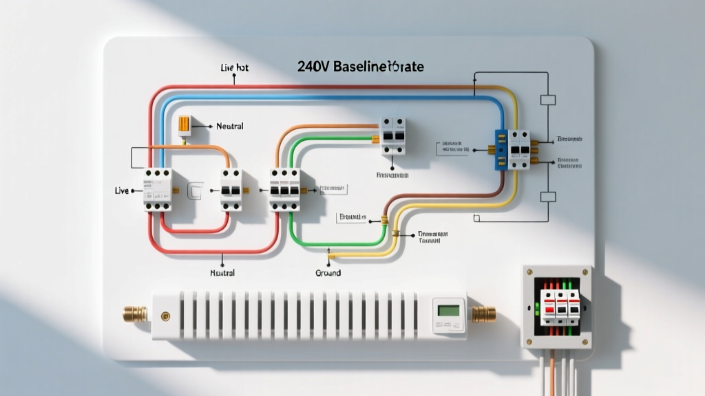
In a motor circuit, we identify Line (L1/L2) and Load (T1/T2). We apply the exact same nomenclature to line-voltage thermostats. A double-pole thermostat breaks both hot legs of the 240V circuit when turned to the 'Off' position, ensuring zero voltage reaches the heating element during maintenance.
⚠️ CRITICAL SAFETY PROTOCOL: Before opening any panel, execute a Lockout/Tagout (LOTO) procedure on the main breaker. Verify zero energy state using a CAT III or CAT IV multimeter at the termination points. Refer to OSHA's Hazardous Energy Control guidelines for proper LOTO implementation.Phase 1: Panel to Thermostat (The Line Side)
- Run the Cable: Route 12/2 NM-B from the 20A double-pole breaker to the thermostat's single-gang or double-gang wall box.
- Identify the Neutral (White) Wire: In a 240V pure-resistive circuit, there is no neutral. The white wire in the 12/2 cable acts as a second hot leg. You must wrap both ends of the white wire with black electrical tape or heat-shrink tubing to re-identify it as a hot conductor per NEC 200.7(C).
- Terminate Line Side: Connect the black wire to the thermostat's L1 terminal. Connect the re-identified white wire to the thermostat's L2 terminal.
- Grounding: Terminate the bare copper ground to the metal wall box (if applicable) and the thermostat's green ground screw.
Phase 2: Thermostat to Heater (The Load Side)
- Run the Cable: Route a second 12/2 NM-B cable from the thermostat box to the baseboard heater's junction box (usually located on either the left or right end cap).
- Terminate Load Side: Connect the black wire to the thermostat's T1 terminal. Connect the re-identified white wire to the T2 terminal.
- Heater Element Connection: Inside the heater junction box, connect the black wire to Heater Lead 1, and the white wire to Heater Lead 2. (Resistive elements are non-polarized; L1/T1 and L2/T2 can be swapped without affecting operation).
- Chassis Ground: Connect the bare ground wire to the green grounding screw inside the heater's junction box. This is critical for tripping the breaker if an element fails and shorts to the metal chassis.
Troubleshooting: Common Failure Modes
When a baseboard heater fails to energize, approach the diagnosis systematically, just as you would trace a faulty motor starter circuit.
1. Heater Hums but Produces No Heat
Diagnosis: This is rare in resistive loads but can occur if the heater is wired for 240V but is only receiving 120V (one hot leg is dead).
Action: Use a multimeter to test voltage across T1 and T2 at the thermostat. If you read 120V instead of 240V, check the double-pole breaker. One pole may have tripped or the internal bus stab in the panel is damaged.
2. Thermostat Clicks but Element Stays Cold
Diagnosis: The internal thermal limit switch has tripped and failed to reset, or the heating element has burned open.
Action: Turn off power. Disconnect the element leads and test continuity across the element with an ohmmeter. A 1000W/240V element should read approximately 57.6 Ohms (R = V² / P). If it reads 'OL' (Open Line), the element is destroyed and the unit must be replaced.
3. Breaker Trips Immediately Upon Energizing
Diagnosis: A dead short. This usually means a wire nut has slipped, or the heating element has physically warped and shorted against the aluminum chassis.
Action: Inspect the element for physical deformation. Ensure all ground wires are isolated from the hot conductors.
2026 Smart Thermostat Integration
If you are upgrading to a smart line-voltage thermostat like the Mysa Smart Baseboard or Sinopé TH1124ZB, the wiring diagram shifts slightly. Smart thermostats require a continuous path for their internal logic boards. While traditional mechanical double-pole thermostats completely sever the circuit when off, smart thermostats often require a 4-wire setup (Line 1, Line 2, Load 1, Load 2) and will trickle a micro-current through the element to power their Wi-Fi radios. Always verify the minimum wattage requirements of smart thermostats; some require at least 150W on the load side to prevent the element from faintly glowing when the unit is 'off'.
For comprehensive energy efficiency data on electric resistance heating versus modern heat pump alternatives, consult the U.S. Department of Energy's Home Heating Systems guide.
Frequently Asked Questions
Can I use a single-pole thermostat for a 240V baseboard heater?
Yes, but it is not recommended. A single-pole thermostat only breaks one hot leg (L1). The heating element remains energized with 120V potential to ground even when turned 'off'. Double-pole thermostats break both legs, providing a true zero-energy state for safety.
Do I need to connect the neutral wire to the baseboard heater?
No. Standard 240V baseboard heaters do not use a neutral wire. They operate purely on two hot legs (Phase A and Phase B). If you are installing a 120V heater, you will use one hot leg, the neutral, and a ground, protected by a single-pole breaker.