
The Stratocaster Circuit: Beyond the Basic Schematic
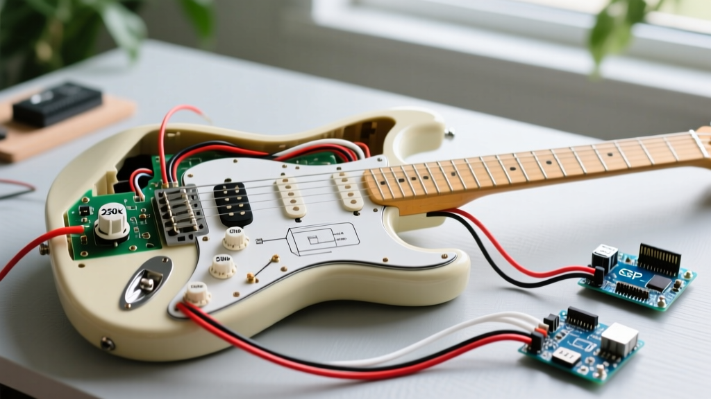
The Fender Stratocaster remains one of the most iconic and heavily modified electric guitars in history. While a standard wiring diagram for Fender Strat models looks deceptively simple on paper, executing a noise-free, reliable, and tone-preserving harness requires a deep understanding of component tolerances, grounding topology, and soldering thermodynamics. In 2026, with the influx of ultra-cheap import potentiometers and switches flooding the market, building a premium wiring harness from scratch is the best way to guarantee studio-grade signal integrity. This guide bypasses generic overviews and provides an expert-level, step-by-step walkthrough for wiring a standard 3-single-coil Stratocaster configuration, complete with modern reliability upgrades.
Bill of Materials (BOM): Premium Component Selection
Do not compromise on passive components. The tolerances of cheap carbon-track pots can vary by up to 20%, drastically altering your taper and high-frequency roll-off. Below is the exact BOM used by professional luthiers for a standard Stratocaster build.
| Component | Specification & Model | Est. Cost (2026) | Why It Matters |
|---|---|---|---|
| Potentiometers (x3) | CTS 450G Series, 250k Audio Taper, Split Shaft | $7.50 / ea | Tight 10% tolerance, smooth audio sweep, 24-spline US spec shaft. |
| Selector Switch | CRL or OakGrigsby 5-Way Lever Switch | $16.00 | Heavy-duty copper contacts prevent arcing and signal dropout. |
| Output Jack | Switchcraft #11 Mono Jack | $4.50 | Nickel-silver construction maintains tension; prevents cable pop-outs. |
| Tone Capacitor | Mallory 150 Series 0.047µF (or 0.022µF) | $3.50 | Metalized polyester film offers tight tolerance and vintage-voiced roll-off. |
| Wire | 22 AWG Stranded Push-Back (Cloth) | $14.00 / spool | Pre-tinned copper, no stripping required, vintage aesthetic. |
| Solder | 63/37 Eutectic Rosin-Core (0.031") | $12.00 | Leaded eutectic melts at a single temperature, preventing cold joints on large ground planes. |
Preparation: Shielding and Thermodynamics
Before picking up your iron, address the cavity. Single-coil pickups are notorious for 60Hz electromagnetic interference (EMI). While traditional copper tape works, applying two coats of a modern conductive shielding paint (such as MG Chemicals 842AR) to the pickup and control cavities provides superior, gap-free Faraday cage protection. Ensure the paint makes contact with the pickguard's aluminum or copper shielding foil when assembled.
Expert Soldering Tip: When grounding wires to the back of CTS potentiometer casings, a 25-watt iron will fail. The massive metal casing acts as a heatsink. Use a temperature-controlled station set to 380°C (715°F) with a chisel tip. Scuff the soldering area with 220-grit sandpaper and apply a dab of flux before tinning the casing. If the solder 'blobs' instead of flowing smoothly, you have a cold joint waiting to cause intermittent grounding failures.
Step-by-Step Wiring Walkthrough
Step 1: Grounding the Potentiometer Casings
The foundation of a noise-free Stratocaster is a star-grounding or daisy-chain grounding scheme. For standard Strat wiring, a daisy-chain across the three pot casings is standard and effective.
- Cut a 4-inch piece of bare 22 AWG solid copper wire.
- Lay it across the back casings of the Volume, Tone 1, and Tone 2 pots.
- Solder the wire securely to each casing. This creates a unified ground bus.
- Solder a ground wire from the Volume pot casing to the Sleeve lug of the Switchcraft #11 output jack.
Step 2: Wiring the CRL 5-Way Selector Switch
Orient your CRL switch so the lugs are facing you. The switch has two sides (Side A and Side B), each with 4 lugs. We will primarily use Side A for inputs and Side B for the output.
- Bridge Pickup Hot: Solder to Lug 1 (Side A).
- Middle Pickup Hot: Solder to Lug 2 (Side A).
- Neck Pickup Hot: Solder to Lug 3 (Side A).
- Output to Volume: Solder a wire from Lug 4 (Side B) to Lug 1 (Input) of the Volume Potentiometer.
- Jumper: Solder a small jumper wire connecting Lug 4 to Lug 5 on Side B. (This ensures the signal reaches the output in positions 1, 3, and 5).
Note: Always wrap the hot leads from your pickups in heat-shrink tubing where they enter the switch lugs to prevent accidental shorting against the copper shield.
Step 3: Connecting Tone Controls and Capacitors
Standard Fender wiring assigns Tone 1 to the Neck pickup and Tone 2 to the Middle pickup, leaving the Bridge pickup without a tone control (a common complaint we will address in the mods section).
- Tone 1 (Neck): Run a wire from the Neck pickup's hot lead (or Switch Lug 3) to Lug 1 of Tone Pot 1.
- Tone 2 (Middle): Run a wire from the Middle pickup's hot lead (or Switch Lug 2) to Lug 1 of Tone Pot 2.
- Capacitor Placement: Solder one leg of the 0.047µF Mallory capacitor to Lug 2 (the wiper) of Tone Pot 1. Solder the other leg to the grounded back casing of the pot. Repeat this exact process for Tone Pot 2 using a second capacitor (or jumper the pots if using a shared cap, though individual caps allow for future value swapping).
- Bend Lug 3 of both tone pots down and solder it directly to the pot casing to ground it.
Step 4: The Output Jack and Tremolo Claw
The Switchcraft #11 jack features a Tip lug (hot) and a Sleeve lug (ground).
- Solder the hot output wire from the Volume Pot (Lug 2 / Wiper) to the Tip lug of the jack.
- Solder the main ground bus wire from the Volume pot casing to the Sleeve lug of the jack.
- Tremolo Claw Ground: Solder a stranded 22 AWG wire to the metal spring claw in the back cavity of the guitar. Route this wire to the control cavity and solder it to the back of the Volume pot casing. This grounds the strings and bridge, which is critical for reducing high-frequency hiss when you touch the strings.
Troubleshooting Common Strat Wiring Failure Modes
Even with a perfect schematic, physical execution errors cause 90% of post-assembly issues. Use this diagnostic matrix before closing up the pickguard.
| Symptom | Root Cause | Corrective Action |
|---|---|---|
| Persistent 60Hz hum that stops when touching strings | Missing or broken ground connection to the tremolo claw or output jack sleeve. | Check continuity from the bridge to the jack sleeve with a multimeter. Re-solder the claw wire. |
| Volume pot acts like a kill-switch (abrupt drop-off) | Wired lugs 1 and 3 backward, or using a Linear taper pot instead of Audio. | Verify CTS 450G Audio taper. Swap hot input and ground wires on the outer lugs. |
| Switch positions 2 and 4 are out of phase (thin, quacky, weak) | Middle pickup hot and ground wires are reversed relative to the outer pickups. | Swap the hot and ground leads of the middle pickup at the switch and ground bus. |
| Scratchy, popping sounds when turning tone knobs | Carbon track debris or oxidation inside the pot casing. | Spray DeoxIT D5 contact cleaner into the pot slot and rotate 50 times. Do not use WD-40. |
Expert Mods: Treble Bleed and Bridge Tone Control
The standard wiring diagram for Fender Strat has two historical flaws: high-frequency loss when rolling back the volume, and a Bridge pickup with no tone control. Here is how to fix both in 2026 without routing the body.
The Treble Bleed Network
As you lower the volume pot, the impedance changes, bleeding off treble frequencies and making the guitar sound muddy. To counteract this, solder a treble bleed circuit across Lug 1 (Input) and Lug 2 (Wiper) of the Volume pot.
- Components: 150kΩ 1/4W metal film resistor in parallel with a 0.001µF (1nF) ceramic or film capacitor.
- Result: Your guitar retains its high-end sparkle and clarity even when the volume is rolled down to 3 or 4, ideal for rhythm-to-lead swells.
Adding Tone Control to the Bridge Pickup
To give the notoriously bright Bridge pickup a tone control, simply run a small jumper wire from Switch Lug 3 (Neck input) to Switch Lug 4 (Bridge input - wait, standard CRL bridge is Lug 1). Correction for standard CRL: The Bridge hot is on Lug 1. To add a tone control, you must jumper the Bridge hot lug (Lug 1) to the Tone 2 input lug, or use a specialized 5-way switch (like the OakGrigsby 4P5T) that features a dedicated tone pole. The easiest non-destructive method is to move the Tone 2 wire from the Middle pickup lug to the Bridge pickup lug on the switch, giving you Neck Tone and Bridge Tone, leaving the Middle pickup wide open.
Authoritative References and Further Reading
For visual schematics and alternative configurations (such as HSS or 7-way Stratocaster mods), consult the following industry-standard libraries:
- StewMac Wiring Kits and Diagrams - Excellent for physical component placement and visual lug orientation.
- Seymour Duncan Wiring Library - The gold standard for color-code matching when upgrading to aftermarket single-coils or humbuckers.
- Fralin Pickups Stratocaster Schematics - Highly detailed guides on advanced mods like the 'Blender' pot and 50s wiring variations.
By adhering to this step-by-step walkthrough and utilizing premium components, your Stratocaster will not only sound indistinguishable from a custom-shop instrument but will also remain gig-ready and noise-free for years to come.