
Mastering the Schematic Electric Fireplace Heater Wiring Diagram
Installing or repairing a built-in electric fireplace insert requires more than just plugging it into a standard wall outlet. Whether you are wiring a high-end Dimplex Revillusion 25-inch insert or a sprawling 60-inch Touchstone Sideline linear unit, understanding the internal and external electrical pathways is critical for safety and performance. A proper schematic electric fireplace heater wiring diagram reveals how line voltage interacts with thermal cutoffs, blower motors, and low-voltage LED flame drivers.
In this comprehensive walkthrough, we break down the exact wiring sequence, circuit requirements, and component-level diagnostics needed for a flawless, code-compliant installation in 2026. We will cover hardwired configurations, dedicated circuit sizing, and specific multimeter testing points to ensure your unit operates safely without tripping AFCI/GFCI breakers.
Hardwired vs. Plug-In: What the Schematic Dictates
Before pulling any wire, you must determine if your specific model requires a hardwired connection or a standard NEMA 5-15R receptacle. Most premium linear fireplaces (like the Amantii Panorama series) and large built-in inserts draw between 1,400W and 1,800W.
- Plug-In (120V/15A): Suitable for units drawing under 1,500W (12.5 Amps). The schematic will show a standard 3-prong pigtail terminating at the main control board.
- Hardwired (120V/20A): Required for units drawing over 1,500W or when local building codes mandate a dedicated junction box for permanent masonry or framed enclosures. The schematic will feature a direct conduit or Romex entry point into the unit's integrated junction box.
Expert Tip: Never use an extension cord or a shared 15-amp lighting circuit for a hardwired electric fireplace. The continuous draw of the heating element combined with the inductive load of the blower motor will cause voltage drop and nuisance breaker trips.
Core Components in the Wiring Schematic
When you trace a schematic electric fireplace heater wiring diagram, you will encounter several distinct sub-circuits. Understanding these nodes is essential for both installation and troubleshooting.
| Component | Function in Schematic | Typical Specifications |
|---|---|---|
| Main Terminal Block | Receives Line (L), Neutral (N), and Ground (G) from the branch circuit. | Rated for 600V, accepts 14-10 AWG solid/stranded wire. |
| KSD301 Thermal Cutoff | Normally closed (NC) bimetallic switch wired in series with the heater element. | Opens at 105°C (221°F) to prevent enclosure fires. |
| Tangential Blower Motor | Distributes heat; often wired through a relay and a run capacitor. | 120V AC, 0.5A to 1.2A draw, uses a 1.5µF to 2.5µF capacitor. |
| LED Flame Driver Board | Steps down 120V AC to low-voltage DC for the flame effect LEDs and motor. | Input: 120V AC / Output: 12V or 24V DC. |
| PTC Heating Element | Positive Temperature Coefficient ceramic heater providing the actual heat. | 750W (Low) / 1500W (High) resistive load. |
Pre-Wiring Preparation & Circuit Sizing
As of the 2026 NEC adoption cycles across most US municipalities, branch circuits supplying heating equipment in living spaces often require dual-function (AFCI/GFCI) protection. According to the National Fire Protection Association (NFPA 70), proper wire gauge and breaker pairing is non-negotiable.
Circuit Sizing Matrix
| Fireplace Max Wattage | Amperage Draw (at 120V) | Required Wire Gauge (NM-B) | Breaker Size & Type |
|---|---|---|---|
| Up to 1,440W | 12.0 Amps | 14 AWG (14/2 with Ground) | 15A Dual-Function (AFCI/GFCI) |
| 1,441W - 1,800W | 12.1 - 15.0 Amps | 12 AWG (12/2 with Ground) | 20A Dual-Function (AFCI/GFCI) |
| Over 1,800W (240V units) | Varies (e.g., 12.5A at 240V) | 12 AWG (12/2 or 12/3) | 20A Double-Pole (240V) |
Note: If your cable run from the panel exceeds 50 feet, upsize to 10 AWG wire to mitigate voltage drop, which can cause the blower motor to overheat and fail prematurely.
Step-by-Step Wiring Walkthrough
Follow this exact sequence when executing your schematic electric fireplace heater wiring diagram for a hardwired 120V, 1500W unit.
Step 1: Rough-In the Dedicated Branch Circuit
- Run a 12/2 NM-B (Romex) cable from your main service panel to the fireplace framing enclosure.
- Install a 20A dual-function breaker (such as the Square D HOM120DF, approx. $55) in the panel. Leave it OFF during the rough-in.
- Terminate the cable into a metal or heavy-duty plastic junction box mounted inside the fireplace framing, ensuring at least 6 inches of wire extends past the box edge.
Step 2: Connect the Main Terminal Block
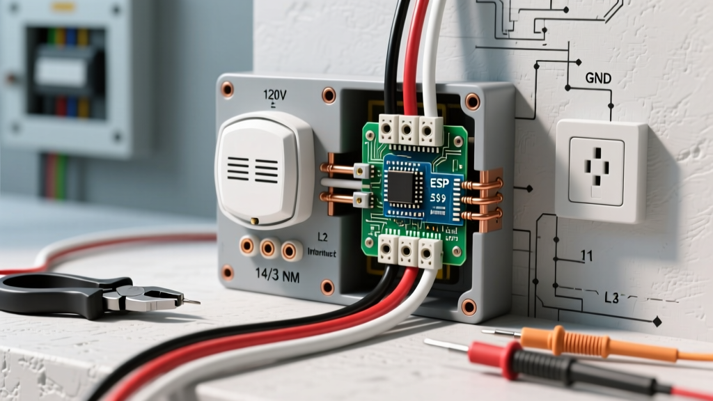
- Strip 3/4 inch of insulation from the black (Line), white (Neutral), and bare (Ground) wires.
- Connect the bare ground wire to the green grounding screw on the fireplace's internal junction box or terminal block. Torque to 12 in-lbs using an insulated torque screwdriver.
- Insert the white Neutral wire into the terminal marked 'N' and tighten the set screw.
- Insert the black Line wire into the terminal marked 'L' or 'L1'.
Step 3: Verify the Thermal Cutoff and Blower Series Circuit
Before closing the enclosure, inspect the internal wiring against the schematic. The hot leg (Line) should route through the main control board relay, then pass through the KSD301 thermal cutoff switch before reaching the PTC heating element.
- Validation: Use a multimeter set to Continuity (or Ohms). Place probes on both sides of the KSD301 switch. It should read near 0.0 Ohms (closed circuit) at room temperature. If it reads 'OL' (Open Line), the thermal fuse is blown and must be replaced before powering on.
Step 4: Integrate the Flame Effect and Blower
The blower motor and LED flame driver operate on separate relays. This allows the user to run the visual flame effect year-round without engaging the 1500W heating element.
- Ensure the blower motor's run capacitor (usually a small black or silver cylinder, 1.5µF) is securely seated in its bracket and its spade connectors are fully pushed onto the motor terminals.
- Verify the low-voltage ribbon cables connecting the main logic board to the LED driver board are fully seated. A loose 12V DC connection will result in flickering flames or a complete failure of the visual effect.
Common Failure Modes & Troubleshooting
Even with a perfect schematic electric fireplace heater wiring diagram execution, components can fail. Use this diagnostic matrix with a True-RMS multimeter (like the Fluke 117) to isolate issues.
| Symptom | Probable Failure Point | Diagnostic Test & Expected Value |
|---|---|---|
| Unit is completely dead (no lights, no sound). | Main thermal fuse blown or lack of line voltage. | Test 'L' to 'N' at terminal block. Expected: 118V-122V AC. If 0V, check breaker. If 120V, test main board fuse. |
| Flame effect works, but no heat and blower won't start. | Heater relay failed or KSD301 tripped open. | Test KSD301 for continuity. Test heater element resistance. Expected: 9 to 11 Ohms for a 1500W element. |
| Blower hums but does not spin. | Failed run capacitor or seized blower bearings. | Test capacitor with multimeter capacitance setting. Expected: 1.5µF ±5%. Replace if reading is below 1.2µF. |
| Breaker trips immediately when heat is turned on. | Shorted PTC element or shared circuit overload. | Verify dedicated circuit. Inspect PTC wiring for melted insulation touching the metal chassis. |
Code Compliance and Safety Standards
When installing permanent electric heating appliances, adherence to safety standards is paramount. The Electrical Safety Foundation International (ESFI) heavily emphasizes the dangers of overloaded circuits and improper clearances with heating equipment.
Furthermore, your chosen fireplace insert should carry a certification mark from a Nationally Recognized Testing Laboratory (NRTL) such as UL (Underwriters Laboratories) or ETL, specifically tested to UL 1278 (Standard for Safety for Moveable and Wall- or Ceiling-Hung Electric Room Heaters). This standard dictates the rigorous thermal cutoff and tip-over switch requirements built into the schematic.
Final Clearance & Enclosure Checks
Before sealing your drywall or stone veneer, verify the following:
- Combustible Clearances: Maintain the manufacturer-specified clearance (usually 0 to 8 inches) from the top of the firebox to any combustible mantel or framing.
- Ventilation: Ensure the bottom intake louver and top exhaust louver are completely unobstructed by insulation or framing debris. Blocked exhaust will trip the KSD301 thermal switch within 3 minutes of operation.
- Junction Box Access: If hardwired, the internal junction box must remain accessible. Do not seal it behind permanent masonry or unremovable facade panels, as this violates NEC Article 314.29 regarding box accessibility.
Conclusion
Decoding a schematic electric fireplace heater wiring diagram is a straightforward process when you approach it methodically. By sizing your dedicated circuit correctly, verifying the continuity of critical safety components like the KSD301 thermal cutoff, and ensuring secure, torqued terminal connections, you guarantee a safe and reliable installation. Always prioritize the manufacturer's specific wiring addendum over generic guides, as logic board layouts and LED driver voltages vary significantly between model years and brands.