
Understanding the Wiring Diagram for Ignition Coil Systems in Gas Appliances
When repairing gas-powered appliances—such as portable Generac generators, Simpson pressure washers, or commercial air compressors—the small engine's ignition system is often the primary suspect for no-start conditions. Unlike complex automotive harnesses, the wiring diagram for ignition coil circuits on small engine appliances is remarkably straightforward, yet it requires precise execution to prevent electromagnetic interference (EMI) and ensure reliable sparking under heavy vibration.
As of 2026, modern EPA Tier 4 and CARB-compliant small engines increasingly utilize digital Capacitor Discharge Ignition (CDI) modules rather than traditional analog magnetos. However, the foundational wiring principles, kill switch grounding circuits, and high-tension (HT) lead routing remain consistent. This tutorial breaks down the exact wiring topology, diagnostic measurements, and edge-case failures you will encounter in the field.
Core Components in an Appliance Ignition Diagram
Before tracing wires, you must identify the nodes on your specific schematic. A standard small engine ignition diagram consists of five critical nodes:
- Flywheel Magnets: The rotating magnetic field that induces voltage in the primary coil.
- Primary Winding: Heavy-gauge copper wire (few turns) that builds the initial magnetic field.
- Secondary Winding: Fine-gauge wire (thousands of turns) that steps up voltage to 15,000–30,000 volts.
- HT Lead (High Tension): The heavily insulated wire routing voltage to the spark plug.
- Kill Switch Circuit: A low-voltage ground wire that shorts the primary winding to halt engine operation.
Magneto vs. CDI: Which Diagram Are You Reading?
Traditional Briggs & Stratton magnetos generate their own spark energy entirely from the flywheel's rotation. The wiring diagram for these coils usually shows only a single spade terminal for the kill switch wire. Conversely, modern digital CDI systems (common on newer Honda Power Equipment and high-end generator engines) require a separate 12V DC power feed from the stator or battery, an ignition trigger pulse wire, and a ground. Always verify whether your appliance uses a self-excited magneto or a powered CDI before applying multimeter probes.
Step-by-Step Appliance Wiring Tutorial: The Kill Switch Circuit
The most common wiring task for appliance repair technicians is replacing a degraded kill switch harness. On gas-powered appliances, the kill switch does not 'cut power' to the coil; instead, it grounds the primary winding, collapsing the magnetic field and preventing the secondary winding from stepping up voltage.
Materials Required
- 16 AWG stranded copper wire (primary circuit grounding)
- Ring terminal (for engine block ground)
- Female spade disconnect (for coil tab)
- Heat shrink tubing and dielectric grease
Wiring Execution Steps
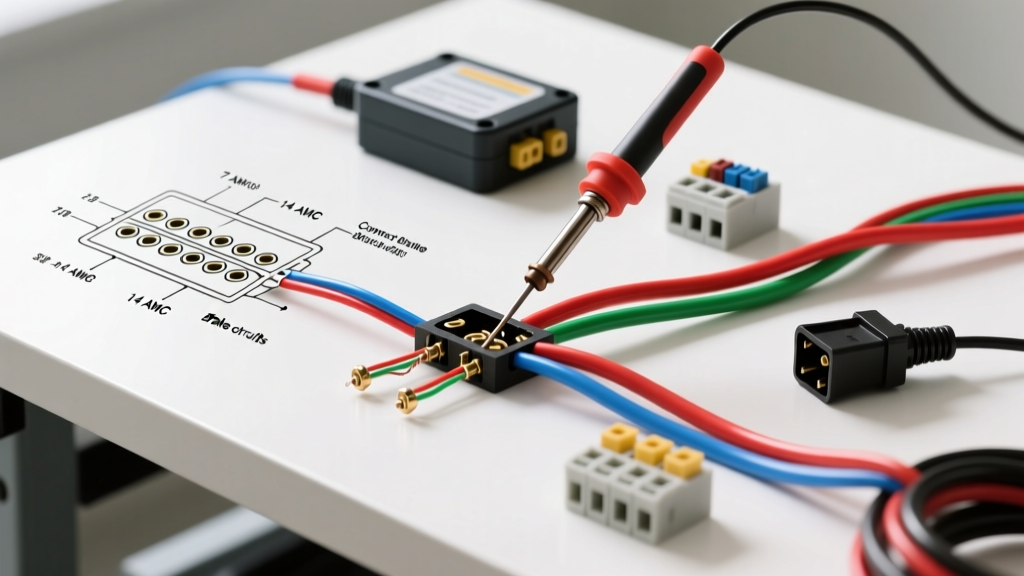
- Route the Ground Wire: Run the 16 AWG wire from the appliance's control panel toggle switch to the engine block. Avoid routing this wire parallel to the alternator/stator AC output wires to prevent inductive feedback.
- Secure the Chassis Ground: Crimp a ring terminal to the engine-block end. Sand away any paint or powder coating on the mounting bolt surface to ensure bare metal-to-metal contact. A poor ground here results in an engine that 'runs on' after the key is turned off.
- Connect to the Coil: Attach the female spade disconnect to the coil's primary ground tab. Apply a dab of dielectric grease to prevent moisture ingress, which is a major failure point in outdoor pressure washers.
- Test the Circuit: With the multimeter set to continuity, place one probe on the coil tab and the other on the engine block. Toggle the switch. You should read 0.0 Ω (closed/grounded) when OFF, and OL (open) when ON.
Diagnostic Table: Multimeter Readings for Common Appliance Coils
When the wiring diagram for ignition coil pathways checks out but the appliance still lacks spark, the coil itself must be bench-tested. Use a digital multimeter (DMM) to measure resistance across the windings. Note that exact specifications vary by OEM, but the following ranges apply to 90% of small engine appliances (160cc to 420cc).
| Component Tested | Expected DMM Reading | Failure Indication & Root Cause |
|---|---|---|
| Primary Winding (Spade to Core) | 0.15 Ω - 0.50 Ω | OL (Open): Internal copper break. Below 0.1 Ω: Internal short. |
| Secondary Winding (HT Lead to Core) | 2,500 Ω - 5,000 Ω | Below 2k Ω: Insulation breakdown between windings. OL: Broken HT lead internal wire. |
| Kill Switch Ground Path | 0.0 Ω (Switch OFF) | Greater than 1.0 Ω: Corroded chassis ground or frayed harness. |
| Coil Lamination to Flywheel | N/A (Feeler Gauge) | Improper air gap causes weak spark or physical collision. |
Crucial Installation Specs: Air Gap and Torque
A perfect wiring diagram is useless if the physical installation parameters are ignored. The magnetic flux density between the flywheel and the coil laminations is highly sensitive to distance.
Expert Specification: The air gap between the ignition coil shoes and the flywheel magnets must be set precisely to 0.010 to 0.012 inches. Use a brass feeler gauge or a standard business card to set this gap before torquing the mounting bolts to 6-8 Nm (53-71 in-lbs). An air gap wider than 0.020 inches will result in a no-spark condition at low cranking speeds, a frequent complaint in recoil-start generators.
Edge Cases: When the Wiring Diagram Lies
Experienced technicians know that electrical symptoms often mask mechanical failures. If your wiring diagram for ignition coil circuits tests perfectly, but the engine backfires or fails to start, investigate these two edge cases:
1. The Sheared Woodruff Key (Timing Shift)
If the appliance (like a commercial floor buffer or pressure washer pump) experienced a sudden mechanical jam, the flywheel's Woodruff key may have sheared. This allows the flywheel to rotate slightly out of phase with the crankshaft. The coil is firing at the exact right time relative to the flywheel, but the wrong time relative to the piston. This mimics a catastrophic ignition wiring failure but requires a mechanical teardown to fix.
2. EMI Interference with the Generator AVR
In portable generators, a degraded HT lead (spark plug wire) can leak high-voltage RF interference into the appliance's chassis. If the HT lead is routed too close to the Automatic Voltage Regulator (AVR) sensing wires, this EMI can cause the AVR to miscalculate the AC output, leading to erratic voltage spikes that trip the appliance's internal breakers. Always maintain a minimum 2-inch clearance between the HT lead and any sensitive AVR or stator wiring, and use braided shielding sleeves where routing constraints are tight.
Frequently Asked Questions (FAQ)
Can I use automotive spark plug wire for a small engine appliance?
While automotive HT wire can conduct the voltage, small engine appliances operate in high-vibration, high-heat environments. Automotive wire boots often lack the specific 90-degree or 180-degree molded shrouds required to seal against small engine cylinder heads, leading to moisture tracking and ground shorts. Always use OEM-specified cut-to-fit small engine HT lead kits.
Why does my generator coil have two wires instead of one?
If your diagram shows two wires connected to the coil (excluding the HT lead), you are likely looking at a charging stator/lighting coil, not the ignition coil. Beginners frequently confuse the stator (which generates AC power for the appliance's alternator section) with the ignition magneto. The ignition coil will always feature a thick, heavily insulated HT lead pointing directly at the spark plug.
Does the kill switch wire need to be shielded?
No. Because the kill switch circuit operates purely as a low-impedance ground path (0V), it is highly immune to induced EMI. Standard 16 AWG stranded copper in a PVC jacket is entirely sufficient for the kill switch harness on outdoor power equipment.