
Understanding the Electrical Load of Tankless Systems
Transitioning to an electric tankless water heater is one of the most effective ways to eliminate standby heat loss and reduce your utility bills. According to the U.S. Department of Energy, tankless systems can be 24% to 34% more energy efficient than conventional storage tank water heaters for homes that use 41 gallons or less of hot water daily. However, this on-demand efficiency comes with a massive, instantaneous electrical demand. Unlike a standard 4500-watt tank heater that draws roughly 18.75 amps on a single 240V circuit, a whole-home 240v electric tankless water heater can draw anywhere from 75 amps to 150 amps.
Before you even look at a wiring diagram, you must verify your electrical panel's capacity. A typical modern home features a 200-amp main service panel. Adding a 27kW tankless unit (which draws 112.5 amps) consumes over half of your panel's total capacity. If your home relies on electric heat, an electric oven, and an EV charger, you will likely need a panel upgrade to 300 or 400 amps, or you must install an automated energy management system (EMS) with load-shedding capabilities to prevent main breaker trips.
240v Electric Tankless Water Heater Wiring Diagram Overview
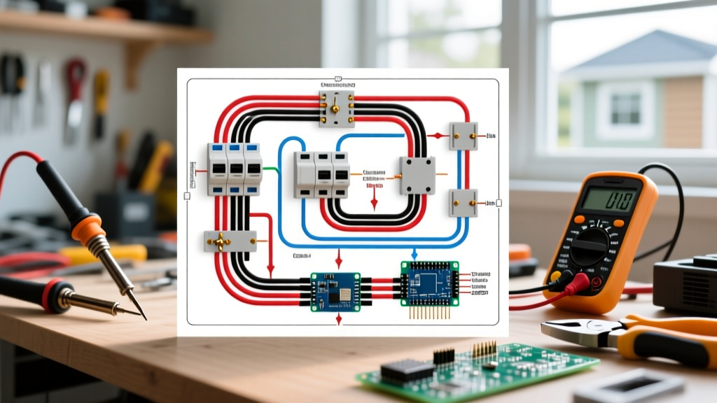
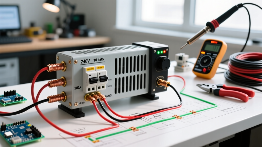
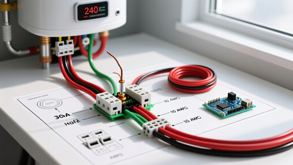
Because we cannot display a graphical schematic here, we will break down the physical topology of the 240v electric tankless water heater wiring diagram. Most high-capacity units (18kW to 36kW) do not use a single circuit. Instead, they utilize multiple parallel heating elements, each requiring its own dedicated double-pole breaker and wire run.
Circuit Routing and Topology
- Main Panel: Multiple 240V double-pole breakers (typically 40A or 50A each) are installed on the bus bars.
- Wire Runs: Individual sets of 2-conductor with ground (or THHN in conduit) run from each breaker directly to the water heater.
- Junction Box (Optional but Recommended): For multi-circuit setups, a large junction box is often mounted adjacent to the unit to consolidate the incoming feeds before entering the heater's internal terminal block.
- Internal Terminal Block: The unit's internal diagram dictates which Line 1 and Line 2 wires connect to specific heating element relays. The bare copper ground wires are bonded to the unit's internal grounding busbar.
Always reference the specific manufacturer's schematic located on the inside of the unit's access cover. Internal relay configurations vary wildly between brands like EcoSmart, Rheem, and Stiebel Eltron.
Model-Specific Breaker and Wire Gauge Matrix
Selecting the correct wire gauge (AWG) and breaker size is critical for fire safety and compliance with the National Electrical Code (NEC). The table below outlines the standard electrical requirements for the most popular whole-home tankless models on the market in 2026.
| Unit Capacity | Example Models | Max Amp Draw | Required Breakers | Wire Gauge (Copper) |
|---|---|---|---|---|
| 18 kW | Rheem RTEX-18, EcoSmart ECO 18 | 75 Amps | 2 x 40A Double-Pole | 2 x 8 AWG |
| 24 kW | Rheem RTEX-24, Stiebel Eltron Tempra 24 | 100 Amps | 2 x 50A Double-Pole | 2 x 6 AWG |
| 27 kW | EcoSmart ECO 27 | 112.5 Amps | 3 x 40A Double-Pole | 3 x 8 AWG |
| 36 kW | EcoSmart ECO 36, Stiebel Eltron Tempra 36 | 150 Amps | 4 x 40A Double-Pole | 4 x 8 AWG |
Note: Wire sizes are based on 60°C/75°C column ratings for NM-B cable or THHN in conduit, adhering to NEC Article 310. Always verify local amendments, as some jurisdictions require conduit (EMT) for all exposed runs.
Step-by-Step Wiring Installation Guide
Step 1: Lockout, Tagout, and Verification
Safety is paramount when working with high-amperage 240V circuits. Turn off the main breaker to de-energize the panel. Use a non-contact voltage tester and a digital multimeter to verify that the bus bars are completely dead. The Electrical Safety Foundation International (ESFI) emphasizes that assuming a panel is dead without testing is a leading cause of residential electrocution.
Step 2: Breaker Installation and Wire Pulling
Install the required double-pole breakers into the panel. Ensure they are firmly seated onto the bus bar stabs. If you are using NM-B (Romex) cable, secure it to the framing within 12 inches of the panel using approved cable staples. If you are pulling THHN/THWN-2 wires through 1/2-inch or 3/4-inch EMT conduit, use a fish tape and wire lubricant to prevent insulation damage. Leave at least 18 inches of slack at the panel and 24 inches at the water heater.
Step 3: Terminations and NEC Torque Requirements
Strip exactly 1/2-inch of insulation from the black and white wires (re-identify the white wire with black electrical tape or heat shrink to signify it is a hot 240V leg). Insert the wires into the breaker terminals.
Crucial 2026 NEC Compliance Note: Under NEC 110.14(D), you are legally required to use a calibrated torque screwdriver to tighten breaker and terminal block lugs to the manufacturer's specified torque value. For most 40A and 50A breakers, this value is between 25 and 35 inch-pounds. Hand-tightening leads to loose connections, which cause high-resistance arcing, melted wire insulation, and eventual breaker failure.
Step 4: Internal Heater Connections
Remove the front cover of the tankless unit. Route the wires through the knockout holes using appropriate cable glands or conduit fittings to prevent the metal casing from slicing the wire insulation. Following the specific 240v electric tankless water heater wiring diagram on the unit:
- Connect the black wires to the designated 'L1' or 'Line 1' terminals on the heating element relays.
- Connect the white wires (marked with black tape) to the 'L2' or 'Line 2' terminals.
- Terminate all bare copper ground wires to the internal green grounding screw or grounding busbar.
Common Wiring Failure Modes and Troubleshooting
Even with a perfect installation, high-draw appliances can reveal underlying electrical weaknesses. Here are the most common failure modes associated with tankless water heater wiring:
- Nuisance Tripping: If a breaker trips immediately upon turning on a hot water tap, the heating element may have failed and shorted to ground, or the wire gauge is undersized for the ambient temperature of the installation space (requiring derating).
- Melted Terminal Blocks: This is almost exclusively caused by failing to use a torque screwdriver. A loose lug creates electrical resistance, which generates intense heat (P = I²R), eventually melting the plastic terminal block.
- Voltage Drop Issues: If the water heater is located more than 100 feet from the main panel, voltage drop can cause the internal logic board to malfunction or the heating elements to underperform. In long runs, you must upsize the wire by one gauge (e.g., use 6 AWG instead of 8 AWG for a 40A circuit).
Frequently Asked Questions
Do I need a GFCI breaker for a hardwired 240V tankless water heater?
Generally, no. The NEC requires GFCI protection for 125V through 250V receptacles (outlets) in specific areas, but hardwired appliances like water heaters are typically exempt unless explicitly mandated by the manufacturer's installation instructions or local AHJ (Authority Having Jurisdiction). Furthermore, the high leakage current of long heating elements can cause nuisance tripping on standard GFCI breakers.
Can I use aluminum wire for my tankless water heater?
While aluminum wire (like 4-4-4-6 SER) is cheaper and often used for main panel feeds, most tankless water heater manufacturers explicitly state in their manuals that internal connections must be made with copper wire only. If you want to use aluminum to save money on long runs, you must transition to copper pigtails using Polaris connectors or a junction box, ensuring you apply antioxidant compound to the aluminum strands.
Where can I find the official codes governing this installation?
All residential wiring must comply with the National Electrical Code (NEC), specifically NFPA 70. Article 422 covers the installation of appliances, while Article 210 and 240 cover branch circuits and overcurrent protection. Always pull a local permit and have the work inspected by your municipal electrical inspector to ensure your home insurance remains valid.