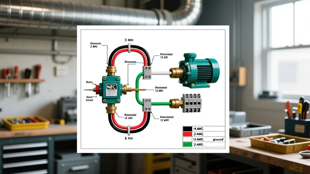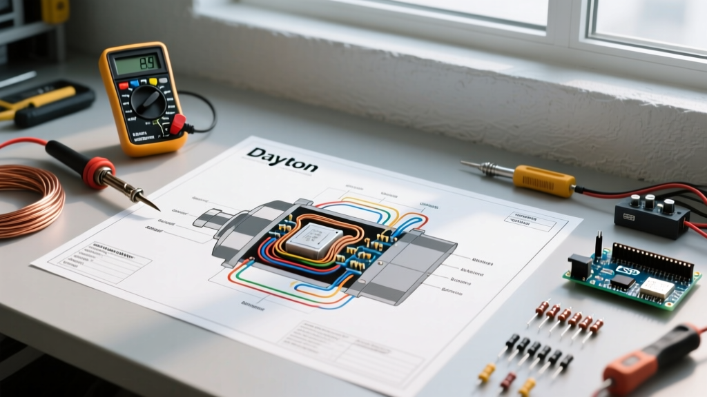

Mastering the Dayton Electric Motors Wiring Diagram for Diagnostics
Dayton electric motors, distributed exclusively by W.W. Grainger, are the undisputed workhorses of North American HVAC, agricultural, and light industrial applications. Whether you are maintaining a 1/2 HP split-phase blower motor or a 5 HP capacitor-start farm duty compressor, the physical wiring schematic tucked inside the peckerhead (connection box) is your primary diagnostic map. When a motor fails to start, hums aggressively, or trips the branch circuit breaker, guessing the fault leads to burned windings and wasted capital. By systematically cross-referencing your multimeter readings with the dayton electric motors wiring diagram, you can isolate failures to the start capacitor, centrifugal switch, or run windings in minutes.
Safety Directive (NFPA 70E): Before removing the peckerhead cover or probing any terminals, execute a full Lockout/Tagout (LOTO) procedure. Verify zero energy state using a CAT III or CAT IV rated multimeter. For comprehensive LOTO protocols, refer to the OSHA Control of Hazardous Energy guidelines.
Decoding NEMA Standards in Dayton Schematics
Dayton motors are manufactured by various global OEMs (such as Nidec, WEG, or Leeson) to Grainger's exact specifications, but they universally adhere to the NEMA MG-1 standard for terminal designations. Understanding these T-lead designations is mandatory before you can troubleshoot.
- T1, T2, T3, T4: These represent the main run windings. In dual-voltage motors, these are split into two separate coils that can be wired in parallel (for 115V) or series (for 230V).
- T5, T8: These represent the start windings and the centrifugal switch circuit. They are only energized during the first 1-3 seconds of motor rotation.
- P1, P2: Often found on Dayton three-phase or specialized single-phase models, denoting thermal protector leads that must be wired in series with the control circuit.
Standard Dayton Dual-Voltage Single-Phase Wiring Matrix
The table below illustrates the standard terminal connections for a typical Dayton 115/230V single-phase capacitor-start motor. Always verify against the specific schematic printed on your motor's nameplate, as lead colors or numbers can vary by manufacturing year.
| Target Voltage | Line 1 (Hot) | Line 2 (Neutral/Hot) | Internal Jumper / Tie | Rotation |
|---|---|---|---|---|
| 115V (Low) | T1, T3, T5 | T2, T4, T8 | None | Standard (CW) |
| 230V (High) | T1, T5 | T4, T8 | T2 tied to T3 | Standard (CW) |
| 115V (Reversed) | T1, T3, T8 | T2, T4, T5 | None | Counter-Clockwise |
Scenario-Based Troubleshooting Using the Diagram
With the wiring diagram decoded, we can apply it to the three most common field failures encountered with Dayton motors in 2026.
Failure Mode 1: Motor Hums Loudly but Will Not Rotate
The Physics: A single-phase motor cannot generate a rotating magnetic field on its own. It requires the start winding (T5/T8) and the start capacitor to create a phase shift. If the motor hums and draws locked-rotor amps (LRA) but doesn't spin, the start circuit has failed.
- Trace the Diagram: Locate the start capacitor and centrifugal switch on your schematic. They are wired in series with each other, and that assembly is in parallel with the run windings.
- Test the Capacitor: Discharge the capacitor safely with a 20k-ohm, 5-watt resistor. Switch your multimeter to capacitance mode (e.g., using a Fluke 87V). A typical Dayton 1/2 HP motor uses a 108-130 µF start capacitor. If your reading is below 95 µF or shows an open circuit (OL), the capacitor is dead. As of 2026, OEM replacement start capacitors (like the Dayton 2MDV5 series) cost between $22 and $38.
- Test the Centrifugal Switch: If the capacitor tests fine, the mechanical centrifugal switch inside the motor housing is likely stuck open or pitted. With the power off, manually rotate the shaft by hand while measuring continuity across T5 and T8. You should hear a distinct 'click' and see continuity close. If it remains open, the switch mechanism requires cleaning or replacement.
Failure Mode 2: Motor Trips Breaker Instantly Upon Energization
The Physics: An instantaneous trip indicates a dead short to ground or a shorted winding, bypassing the magnetic impedance of the coils.
- Megohmmeter Testing: Standard multimeters lack the voltage to detect insulation breakdown. Use an insulation multimeter (like the Fluke 1587) set to 500V DC. Consult the Fluke motor troubleshooting guidelines for exact safety protocols.
- Ground Fault Check: Place the positive lead on T1 and the negative lead on the bare metal motor casing. A healthy Dayton motor should read >100 Megohms. A reading below 1 Megohm indicates compromised winding insulation, often due to moisture ingress in agricultural environments. The motor must be rewound or replaced.
- Winding Short Check: Measure resistance across the run windings (T1 to T2, and T3 to T4). The resistance should be very low (typically 1.5 to 4.0 ohms depending on HP). If one coil reads 0.0 ohms, an internal turn-to-turn short has occurred.
Failure Mode 3: Motor Runs in the Wrong Direction
This is incredibly common when replacing a Dayton motor on an existing belt-driven blower or pump. The wiring diagram makes reversing rotation straightforward.
- The Rule: To reverse a single-phase Dayton motor, you must reverse the polarity of the start winding relative to the run winding.
- The Execution: Looking at the wiring matrix above, if your motor is wired for 115V standard rotation (T5 to Line 1, T8 to Line 2), simply swap T5 and T8. Do not swap Line 1 and Line 2 at the main power source; swapping the incoming AC legs does nothing to change rotation on a single-phase motor.
The VFD Trap: A Warning for Dayton Single-Phase Motors
A frequent and costly mistake made by DIYers and junior technicians is attempting to control the speed of a single-phase Dayton capacitor-start motor using a Variable Frequency Drive (VFD). Do not do this. VFDs output high-frequency PWM (Pulse Width Modulation) waveforms. These high-frequency spikes will instantly destroy the dielectric fluid inside the start capacitor and cause the centrifugal switch to arc and weld shut. If you require variable speed control, you must upgrade to a Dayton 3-phase inverter-duty motor (e.g., the Dayton 4WWG series) paired with a matched VFD, or use a mechanical variable speed pulley system.
Summary of Diagnostic Tools for 2026
To effectively troubleshoot using any Dayton schematic, ensure your toolkit includes:
- True-RMS Digital Multimeter: Essential for accurate capacitance and low-ohm resistance readings.
- Insulation Tester (Megger): Mandatory for verifying winding integrity against the stator frame.
- Non-Contact Voltage Tester (NCVT): For initial LOTO verification before touching the peckerhead terminals.
By treating the Dayton electric motors wiring diagram not just as an installation guide, but as a logical flowchart for electrical diagnostics, you eliminate guesswork, ensure operator safety, and extend the operational lifespan of your critical machinery.