
The Critical Flaw in Most Edelbrock Choke Wiring Jobs
Upgrading from a divorced heat-tube choke to an electric choke is one of the most reliable improvements you can make to a classic V8. However, a shocking number of enthusiasts ruin their cold-start drivability by misinterpreting the Edelbrock electric choke wiring diagram. The most common and destructive mistake? Tapping into the ignition coil’s positive terminal or the factory ballast resistor wire. While these sources provide 12V during the ‘crank’ phase, they drop to 7V–9V once the engine is running. Because the Edelbrock electric choke cap (part #1933 or #1478) requires a full 12V to properly heat the internal bimetallic spring, wiring it to a ballast-fed circuit causes the choke plate to stay partially closed. The result is a perpetually rich mixture, fouled spark plugs, and terrible fuel economy.
In this comprehensive reference guide, we will break down the exact wiring schematic, voltage requirements, grounding workarounds for phenolic spacers, and the mechanical calibration steps necessary to get your Edelbrock Performer or Thunder Series carburetor running flawlessly in 2026.
Anatomy of the Edelbrock Electric Choke Circuit
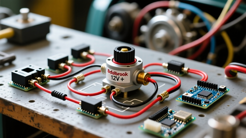
Before running wires, it is vital to understand the electrical load and physical components of the system. The Edelbrock electric choke conversion kit (retailing for approximately $58–$65 in 2026) replaces the vacuum or heat-stove operated diaphragm with a self-contained electrical heating element.
- Heating Element Resistance: Typically 10 to 15 ohms.
- Current Draw: Less than 1 amp (approx. 0.8A at 12V).
- Wire Gauge Requirement: 16 AWG is more than sufficient for the low amperage, though 14 AWG is often used for physical durability in engine bays.
- Operating Time: Requires 3 to 5 minutes of continuous 12V power to fully open the choke plate at 70°F ambient temperature.
Because the current draw is under 1 amp, you do not need a heavy-duty relay. A simple 2A or 5A inline fuse integrated into the switched 12V feed wire is all that is required to protect the circuit from a dead short.
Step-by-Step Edelbrock Electric Choke Wiring Diagram Reference
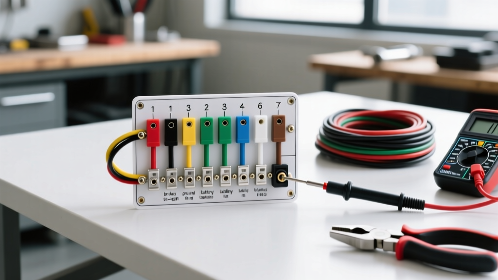
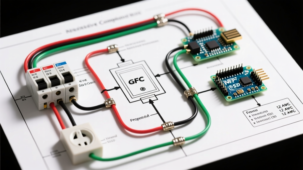
Since physical schematics can be ambiguous, here is the precise textual wiring diagram for the Edelbrock electric choke circuit. Follow this path exactly to ensure safe and reliable operation.
Pro-Tip: Always use a weather-pack connector or high-temperature heat shrink when making connections near the carburetor. Engine bay temperatures and fuel vapors will quickly degrade standard electrical tape and butt connectors.
- Power Source: Identify a true ‘Switched 12V’ source (see voltage table below).
- Fusing: Install a 5A inline ATC/ATO fuse holder within 6 inches of the power source connection.
- Positive Feed: Run a 16 AWG wire from the fuse holder to the positive (+) terminal on the Edelbrock choke cap. The cap terminals are usually marked, but if not, the terminal closest to the index mark is typically positive (though polarity on a simple resistive heating element rarely matters, adhering to markings is best practice).
- Ground Path: The negative (-) terminal on the choke cap grounds internally through the cap’s mounting bracket, into the carburetor base, and down through the intake manifold to the engine block.
Finding the Correct Switched 12V Source
Selecting the right power source is where 90% of wiring errors occur. With the rise of modern 1-wire alternators and aftermarket fuse blocks (like Painless Performance or American Autowire) in restomod builds, finding a clean 12V source is easier than ever, provided you know what to test with a digital multimeter.
| Power Source Location | Voltage (Key On, Engine Off) | Voltage (Engine Running) | Verdict |
|---|---|---|---|
| Ignition Coil (+) Terminal | 12.4V | 8.5V – 9.5V (w/ Ballast) | FAIL (Choke will starve and stall open) |
| Ignition Coil (-) Terminal | 0.0V | Pulsing Ground Signal | FAIL (Will damage cap or fry points) |
| Factory Radio / ACC Fuse | 12.4V | 13.8V – 14.4V | PASS (Ideal for most classic cars) |
| Aftermarket Fuse Block (IGN) | 12.4V | 13.8V – 14.4V | PASS (Best for restomods) |
| Ignition Switch ‘I’ Terminal | 12.4V | 13.8V – 14.4V | PASS (Requires running wire through firewall) |
For authoritative guidance on classic vehicle electrical system upgrades and avoiding voltage drop issues, refer to the Hemmings Classic Car Tech Archives, which frequently detail the nuances of factory resistance wires in Mopar and Ford applications.
The Grounding Dilemma: Intake Isolators and Paint
The standard Edelbrock electric choke wiring diagram assumes a bare metal-to-metal ground path from the carburetor base to the intake manifold. However, modern tuning practices often involve installing a phenolic heat isolator spacer (such as Edelbrock part #9266) between the carburetor and the intake to prevent fuel percolation. Additionally, many show-quality engine bays feature painted intake manifolds or powder-coated carburetor linkage brackets.
Both phenolic spacers and paint act as electrical insulators. If your ground path is compromised, the choke cap will not heat up, and the engine will remain on full choke indefinitely, flooding the cylinders.
The Dedicated Ground Wire Solution
If you are using a spacer or suspect a poor ground, you must modify the standard diagram:
- Attach a 16 AWG wire to the negative (-) terminal on the choke cap.
- Route this wire away from the exhaust headers and moving throttle linkage.
- Secure the other end to a clean, bare-metal bolt on the engine block or cylinder head.
Diagnostic Test: To verify your ground, set your multimeter to DC Volts. Place the red probe on the choke cap’s positive terminal and the black probe on the engine block. With the key in the ‘ON’ position, you should read full battery voltage (12.4V+). If you read 0V, your ground or power feed is open.
Calibration: Setting the Bimetallic Spring Index
Wiring the choke correctly is only half the battle. The electrical heat must be synchronized with the mechanical index of the bimetallic spring. For a complete overview of Edelbrock’s carburetor tuning parameters, consult the Edelbrock Performer Series Carburetors official documentation.
Cold Weather vs. Warm Weather Adjustments
The black plastic choke cap features a scribe mark that aligns with a scale on the aluminum housing. This scale dictates how tightly the spring pulls the choke plate shut when cold.
- Baseline Setting: Align the mark on the cap exactly with the center index line on the housing.
- Lean Adjustment (Warmer Climates): Rotate the cap clockwise 1/4 to 1/2 turn. This reduces spring tension, allowing the choke to open faster and preventing a rich stumble in hot weather.
- Rich Adjustment (Colder Climates): Rotate the cap counter-clockwise 1/4 to 1 turn. This increases spring tension, keeping the choke closed longer for high-altitude or freezing-weather starts.
Fast Idle Cam Setup: When the choke plate is fully closed (engine stone cold), the primary throttle linkage must rest on the highest step of the fast idle cam. The primary throttle plate should have a gap of exactly 1/4" to 3/8" (measured with a drill bit) from the edge of the throttle bore. If the gap is too small, the engine will choke itself; too large, and it will idle at 2,500+ RPM on startup.
Troubleshooting Common Failure Modes
Even with a perfect Edelbrock electric choke wiring diagram execution, environmental factors and component fatigue can cause issues. Use this diagnostic matrix to solve drivability problems:
- Symptom: Choke never opens, engine runs extremely rich after 5 minutes.
Cause: Blown inline fuse, broken heating element inside the cap, or a painted intake manifold blocking the ground.
Fix: Test cap resistance. If it reads ‘OL’ (Open Loop) on a multimeter, the internal wire is snapped. Replace the cap (approx. $25). - Symptom: Choke opens too fast, engine stumbles and dies when cold.
Cause: Cap index set too lean (clockwise), or the fast idle cam is dropping off the step before the engine can sustain its own idle.
Fix: Rotate cap counter-clockwise 1/2 turn and verify the 1/4" throttle plate gap. - Symptom: Intermittent choke operation.
Cause: Vibration loosening the spade connector on the cap, or a frayed wire rubbing against the valve cover.
Fix: Use a silicone boot over the spade connector and secure the wire with high-temp zip ties away from sharp edges. - Symptom: Choke works, but engine hesitates when tapping the throttle cold.
Cause: The choke pull-off diaphragm (if equipped on your specific model) is ruptured or the vacuum line is cracked, failing to crack the choke plate open slightly upon initial startup.
Fix: Apply manifold vacuum to the pull-off and ensure it retracts the linkage by at least 1/8".
By respecting the electrical requirements of the 12V heating element and pairing it with precise mechanical adjustments, your Edelbrock carburetor will deliver modern, turn-key starting reliability without sacrificing classic V8 character.