
The Motor Control Approach to Residential and Commercial Lighting
When industrial electricians and motor control technicians transition to facility lighting, they rarely treat a simple lighting circuit as an afterthought. In motor control panels, a 120V control circuit transformer powers everything from PLC logic to panel illumination, and those circuits are wired with the exact same rigor as a 480V three-phase feeder. If you are searching for a wiring diagram for two lights on one switch, you are likely looking at a fundamental branch circuit. However, applying an industrial, motor-wiring perspective to this diagram reveals critical nuances regarding continuous loads, termination torque, and modern LED inrush currents that standard DIY guides completely ignore.
In 2026, with the widespread adoption of high-efficacy LED drivers and the strict enforcement of NEC Article 110.14(D) regarding calibrated torque tools, wiring two lights to a single pole switch requires precision. This guide breaks down the schematic, wire sizing, and advanced contactor-relay adaptations necessary to ensure your lighting circuit operates safely and reliably for decades.
Core Components and NEC Sizing Rules
Before pulling any wire, we must establish the baseline parameters of the circuit. In motor wiring, we size conductors based on the Full Load Amps (FLA) of the motor plus a 125% safety factor. For lighting, NEC Article 210 requires similar foresight, especially for continuous loads (those expected to run for 3 hours or more).
| Parameter | 14 AWG Copper (THHN/THWN) | 12 AWG Copper (THHN/THWN) |
|---|---|---|
| Max Overcurrent Protection | 15 Amps (NEC 240.4(D)) | 20 Amps |
| Max Continuous Load (120V) | 1,440 Watts (12A) | 1,920 Watts (16A) |
| Conductor Diameter | 1.63 mm (Solid) | 2.05 mm (Solid) |
| Terminal Torque Spec (Typical) | 12 in-lbs | 14-16 in-lbs |
| Best Use Case | Standard residential rooms, low-draw LEDs | Commercial bays, long runs, high-inrush LEDs |
According to the Copper Development Association, voltage drop is a major factor in long commercial runs. If your switch is located more than 50 feet from the furthest light fixture, step up to 12 AWG even if the breaker is only 15A, to maintain optimal voltage at the LED driver.
Step-by-Step: Standard Single-Pole Wiring Diagram
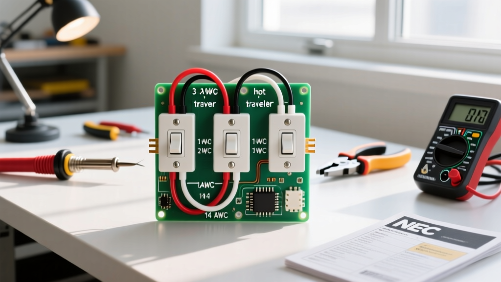
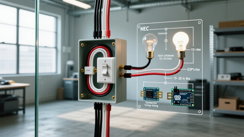
The standard topology for a wiring diagram for two lights on one switch relies on a 'Line-to-Load' configuration where the main power enters the switch box first. This is vastly superior to the outdated 'switch loop' method, as it provides a neutral wire in the switch box—a strict requirement for modern smart switches and occupancy sensors under current NEC Article 404.2.
Phase 1: Preparing the Switch Box (Line and Neutral)
- Lockout/Tagout (LOTO): Always verify zero energy. Follow strict OSHA LOTO procedures and test the conductors with a CAT III rated non-contact voltage tester and a digital multimeter.
- Land the Grounds: Pigtail all bare copper or green equipment grounding conductors (EGC) together using a WAGO 221-413 lever nut or an Ideal Green 72B wire nut. Run a single 14 AWG pigtail to the green grounding screw on the single-pole switch (e.g., Leviton Decora 5601).
- Splice the Neutrals: Connect the incoming Line Neutral (white) directly to the Neutral wire heading to Light 1. The switch does not interrupt the neutral. Push these into the back of the box to keep the wiring cavity clear.
- Terminate the Line Hot: Connect the incoming Line Hot (black) to the bottom brass terminal of the switch. Torque to the manufacturer's specification (typically 12 in-lbs).
Phase 2: The Load Side and Daisy-Chaining the Second Light
- Switched Hot to Light 1: Connect a black pigtail to the top brass terminal of the switch. This is your 'Switched Hot'. Route this conductor out of the switch box and into the junction box of Light Fixture 1.
- Fixture 1 to Fixture 2 (The Daisy Chain): At Light Fixture 1, you will have three sets of wires: the incoming Switched Hot from the switch, the outgoing cable to Light 2, and the fixture's internal leads. Connect the incoming Switched Hot, the outgoing black wire to Light 2, and the black lead of Fixture 1 together.
- Complete Fixture 2: At Light Fixture 2, simply connect the incoming black wire to the fixture's black lead, the white to white, and ground to ground.
Pro-Tip from the Panel Shop: Never use the push-in 'backstab' terminals on residential switches. They rely on a tiny spring-steel wedge that can loosen over time due to thermal cycling, leading to high-resistance faults and arcing. Always use the side-clamp screw terminals or the screw-actuated clamp plates found on commercial-grade switches.
Advanced Scenario: High-Inrush LEDs and Lighting Contactors
Here is where the motor wiring perspective becomes critical. If your 'two lights' are actually 200W commercial high-bay LED fixtures, you are not just dealing with steady-state current. LED drivers contain massive internal capacitors. Upon startup, these capacitors draw an inrush current that can be 50 to 100 times the steady-state operating current for a fraction of a millisecond.
For a 200W fixture drawing 1.6A steady-state, the inrush can briefly spike to 120A. If you switch two of these on a standard 15A residential toggle switch, the micro-arcing across the closing contacts will quickly pit and weld the switch internals, causing premature failure.
The Contactor Solution
To solve this, we adapt motor-control logic. Instead of routing the load directly through the wall switch, we use the wall switch to control the coil of a lighting contactor.
- The Pilot Switch: The wall switch only handles the 0.1A draw of the contactor coil (e.g., an Eaton C50CN 120V coil).
- The Contactor: An enclosed lighting contactor mounted in the ceiling junction box handles the heavy 120A inrush spikes. Contactors like the Schneider Electric 8903 series are designed with heavy silver-alloy contacts specifically rated for high-inrush LED and HID lighting loads.
This setup guarantees that your wall switch will last for millions of cycles, as it is entirely isolated from the destructive inrush currents of the LED drivers.
Troubleshooting Matrix: Common Lighting Circuit Faults
When a newly wired circuit fails to operate, use this diagnostic matrix before tearing open the drywall.
| Symptom | Probable Cause (Motor Tech Diagnosis) | Corrective Action |
|---|---|---|
| Breaker trips instantly upon switch closure | Dead short. Switched Hot is touching Ground or Neutral, or fixture ballast/driver is internally shorted. | Megger test the Switched Hot conductor to ground at 500V DC. Inspect fixture driver for moisture ingress. |
| Lights flicker when the switch is toggled | Loose termination causing micro-arcing, or incompatible dimmer switch interacting with LED driver. | Verify torque specs on all wire nuts and terminal screws. Replace standard dimmer with an ELV/MLV rated LED dimmer (e.g., Lutron Diva). |
| Switch feels warm to the touch after 1 hour | Overloaded switch. Continuous load exceeds 80% of switch rating (12A on a 15A switch). | Upgrade to a 20A commercial switch or implement the lighting contactor method detailed above. |
| Neutral wire in switch box shows 120V | Open neutral upstream. The return path is broken, and the neutral is floating at line potential through the load. | Trace the neutral back to the panel. Check for a failed WAGO lever-nut connection or a broken staple pinch. |
Final Verification and Commissioning
Before energizing the circuit, perform a continuity check. With the power still locked out and the switch in the 'OFF' position, place your multimeter leads on the Line Hot and the Switched Hot. You should read infinite resistance (OL). Flip the switch to 'ON'; you should read near 0.0 ohms. Finally, verify that the Equipment Grounding Conductor has continuous continuity from the panel ground bar all the way to the metal housing of both light fixtures. By treating a simple lighting diagram with the respect and rigorous testing protocols of a motor control circuit, you ensure a safe, code-compliant, and permanent installation.