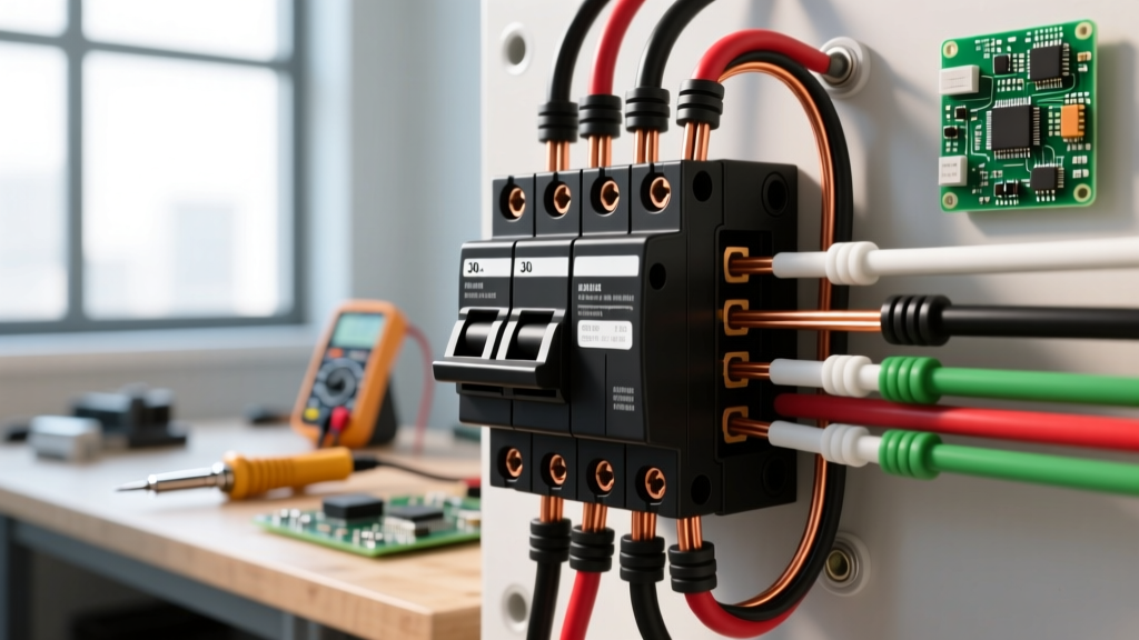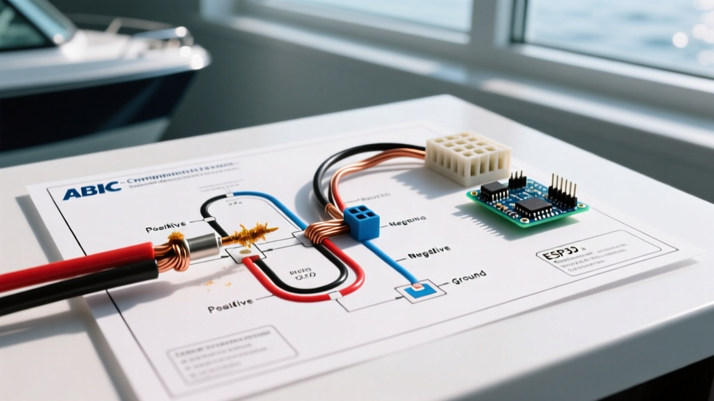

The Anatomy of a Marine-Grade Schematic
When you sit down to draft or interpret a wiring diagram for boat applications, you are not just mapping electrical flow; you are engineering a lifeline. Marine environments are uniquely hostile to electrical systems. Saltwater spray, constant vibration, UV exposure, and extreme temperature fluctuations turn minor wiring flaws into catastrophic failures, including galvanic corrosion, voltage starvation, and electrical fires. Unlike automotive or residential wiring, a marine schematic must account for isolated grounds, strict overcurrent placement, and specialized conductor materials.
In 2026, with the rapid adoption of high-draw lithium iron phosphate (LiFePO4) battery banks and advanced digital switching systems like CZone, understanding the foundational safety codes governing DC marine electrical systems is more critical than ever. This guide breaks down the American Boat and Yacht Council (ABYC) E-11 standards to help you design, read, and troubleshoot safe, compliant boat wiring diagrams.
ABYC E-11 Compliance: The Gold Standard
The ABYC E-11 standard dictates the rules for AC and DC electrical systems on boats. While not legally mandated by the US Coast Guard for all vessel types, it is the undisputed benchmark for marine safety, insurance underwriting, and professional boat building. A compliant wiring diagram for boat DC circuits must explicitly address three core areas: voltage drop tolerances, conductor sizing, and overcurrent protection placement.
Voltage Drop Tolerances and Calculations
Marine electronics and navigation equipment are highly sensitive to voltage starvation. The ABYC mandates specific maximum voltage drop limits based on the circuit's purpose:
- 3% Maximum Drop: Required for navigation lights, bilge blowers, and sensitive marine electronics (e.g., Garmin or Raymarine chartplotters, VHF radios).
- 10% Maximum Drop: Permitted for general accessories like cabin lighting, wipers, and non-critical DC receptacles.
To calculate the required wire gauge for your schematic, use the Circular Mil (CM) formula:
CM = (2 × K × I × L) / VD
- K = Resistivity of copper (approx. 10.75 for tinned marine wire at 77°F)
- I = Current in amps
- L = Total length of the circuit (positive + negative run in feet)
- VD = Allowable voltage drop (e.g., 0.36V for a 3% drop on a 12V system)
For example, running a 5A windlass 15 feet from the battery (30 feet total wire length) with a 3% allowable drop requires a minimum of 10 AWG wire. Your wiring diagram must annotate these calculated gauges clearly next to each circuit line.
Decoding the Wiring Diagram for Boat Color Codes
Standardizing wire colors prevents lethal confusion between AC and DC systems, and between positive and negative conductors. Below is the ABYC-mandated color code matrix that must be reflected in your schematic legend.
| Wire Color | Designation | Application & Notes |
|---|---|---|
| Red | DC Positive | Main battery feeds and unswitched positive conductors. |
| Yellow or Black | DC Negative | ABYC allows black, but yellow is highly preferred in marine DC to prevent confusion with AC hot (black) wires. |
| Red w/ Black Tracer | Fused DC Accessory | Switched positive wires running from a fuse block to a specific accessory. |
| White | AC Neutral | Strictly reserved for AC shore power or inverter neutral. Never use for DC. |
| Green | AC Ground / DC Bonding | Used for AC grounding and DC bonding systems to prevent galvanic corrosion. |
Wire Selection: Tinned Copper and Type III Stranding
A professional marine schematic will specify tinned, marine-grade copper wire (UL 1426 or SAE J1128). Standard automotive wire uses untinned copper with thick, stiff strands. In a marine environment, untinned copper quickly oxidizes, turning black and creating high-resistance points that generate heat and cause fires. Tinned wire features a microscopic coating of tin on every individual copper strand, halting capillary action and preventing moisture from wicking up the wire jacket.
Furthermore, marine wire utilizes Type III stranding, which features significantly more, finer strands than automotive wire. This flexibility is crucial for absorbing the constant vibration of a boat hull without suffering from metal fatigue and internal strand breakage. As of 2026, premium brands like Ancor Marine charge roughly $1.25 to $1.80 per foot for 10 AWG tinned wire—a necessary investment over cheaper $0.40/ft automotive alternatives.
Overcurrent Protection and the "7-Inch Rule"
The most critical safety annotation on any wiring diagram for boat DC systems is the location of overcurrent protection (fuses or circuit breakers). The ABYC E-11 standard enforces the 7-Inch Rule: every positive conductor must be protected by a fuse or breaker within 7 inches of the power source (the battery positive terminal).
If the wire is enclosed in a continuous sheath or conduit, this distance can be extended to 72 inches, but the 7-inch rule is the safest baseline. For the main battery feed, your schematic should specify a Marine Rated Battery Fuse (MRBF), such as the Blue Sea Systems 5191 series, mounted directly on the battery post. For branch circuits, specify a centralized fuse block like the Blue Sea Systems ST Blade series, ensuring the feed wire from the battery to the fuse block is appropriately gauged to handle the cumulative amperage of all branch circuits.
Expert Insight: Never place a main DC disconnect switch on the negative side of the battery bank. Always switch the positive side. If a negative switch fails or is left on while the positive is disconnected, the boat's DC bonding system can remain energized relative to the water, accelerating galvanic corrosion of your propeller and shaft.
Critical Edge Case: Bilge Pump Wiring
Bilge pumps represent a unique failure mode that must be explicitly detailed in your schematic. A bilge pump must be wired directly to the battery positive via its own dedicated fuse, bypassing the main DC distribution panel and the main battery disconnect switch. If a boat is taking on water, the bilge pump must operate even if the captain has shut off all other DC power to prevent a fire. The fuse for the bilge pump must be located at the battery (not down in the wet bilge), and the wiring must be routed high above the waterline to prevent a short circuit from disabling the pump before the fuse blows.
Drafting Your Schematic: Tools and Best Practices
While hand-drawn schematics are acceptable if they use standard IEEE/IEC symbols, digital drafting ensures clarity and easy updates. When designing your layout, leverage the extensive circuit architecture guides available through Blue Sea Systems resources, which provide excellent templates for dual-battery setups and ACR (Automatic Charging Relay) integration.
Ensure your final diagram includes:
- Bill of Materials (BOM): Exact wire gauges, lengths, and terminal types (e.g., adhesive-lined heat shrink ring terminals).
- Fuse Ratings: Amperage and interrupt capacity (AIC) for every protection device.
- Connection Points: Bus bars, terminal blocks, and switch models.
- Revision History: Date and author of the latest schematic update.
Final Inspections and Maintenance
A wiring diagram is a living document. As you add solar panels, upgrade to lithium batteries with internal BMS, or install new thrusters, the schematic must be updated. For ongoing maintenance and safety inspection checklists, refer to the BoatUS expert advice archives, which provide excellent seasonal electrical audit protocols. By strictly adhering to ABYC standards and maintaining an accurate, detailed wiring diagram for your boat, you ensure that your vessel remains safe, reliable, and insurable for years to come.