
Understanding the Square D Pressure Switch Architecture
When maintaining or installing a residential well system, mastering the wiring diagram for Square D pressure switch assemblies is a fundamental skill for any DIY electrician or homeowner. Schneider Electric’s Square D brand, specifically the 9013FSG and 9013FHG series, remains the industry standard for fluid and air pressure control in 2026. For submersible and jet well pumps, the Square D 9013FSG2 (typically pre-calibrated to 30/50 PSI) is the most ubiquitous model on the market, retailing between $18 and $26 depending on the supplier.
Unlike solid-state relays, the FSG2 utilizes a mechanical diaphragm and spring-loaded contact block. This electromechanical design is highly resilient to voltage spikes common in rural well houses but requires precise wiring and torque specifications to prevent contact pitting and premature failure.
FSG vs. FHG: Knowing Your Application
- 9013FSG Series: Designed for water pumps. It features a simple snap-action contact mechanism without an unloader valve. Ideal for submersible and shallow jet pumps.
- 9013FHG Series: Designed for air compressors. It includes an integrated unloader valve that bleeds trapped air from the compressor head when the motor stops, allowing for an unloaded restart.
Essential Tools and 2026 Material Costs
Before opening the switch housing, ensure you have the correct materials. Due to copper market fluctuations in early 2026, expect to pay a premium for UF-B (Underground Feeder) and THHN wire.
- Square D 9013FSG2 Pressure Switch: ~$22.00
- 12 AWG or 10 AWG Wire (2-conductor with ground): ~$0.65 - $0.90 per foot
- Wire Strippers (e.g., Klein Tools 11055): ~$28.00
- Torque Screwdriver (calibrated to 12-14 in-lbs): ~$45.00
- CAT III Digital Multimeter (e.g., Fluke 117): ~$190.00
Step-by-Step Wiring Diagram for Square D 9013FSG2 (240V)
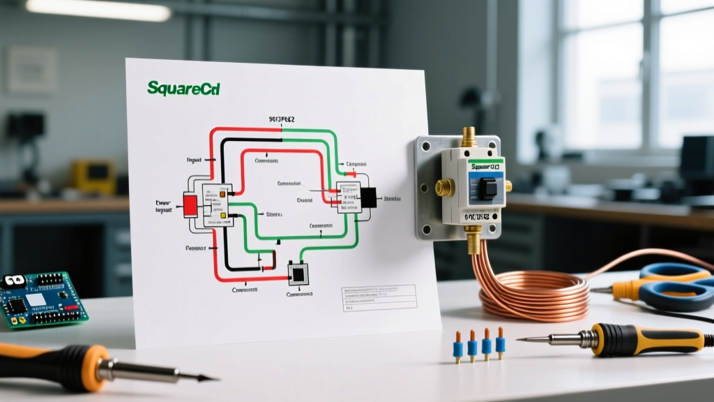
Most residential submersible pumps operate on a 240V dedicated circuit protected by a 30-amp double-pole breaker. Below is the exact terminal routing for the FSG2 switch.
Safety & Code Compliance: According to the National Electrical Code (NEC) Article 430, motor circuits require specific overcurrent protection and grounding protocols. Always lock out and tag out (LOTO) the main breaker before servicing well equipment. Verify zero voltage with a multimeter before touching any terminals.
- Ground Connection (First Step): Strip the bare copper ground wire to 3/4 inch. Connect it to the green grounding screw located on the metal mounting plate of the switch housing. Torque to 12 in-lbs. Never use the terminal block screws for grounding.
- Line Side (Power In): Route your incoming 240V cable through the left-side knockout. Connect the two hot wires (typically black and red, or black and white re-identified with black tape) to the Line 1 and Line 2 terminals on the left side of the contact block.
- Load Side (Pump Out): Route the pump cable through the right-side knockout. Connect the pump’s hot wires to the Load 1 and Load 2 terminals on the right side of the contact block.
- Secure and Seal: Ensure no stray wire strands are bridging the gap between Line and Load. Clamp the cables securely using proper Romex connectors. Replace the plastic cover.
Wire Gauge Selection Matrix for Submersible Pumps
One of the most common errors in well pump wiring is voltage drop caused by undersized wire over long trench runs. The EPA guidelines for private well systems emphasize maintaining voltage within 5% of the motor’s nameplate rating. Use the matrix below to select the correct copper wire gauge based on pump horsepower (HP) and the total one-way distance from the breaker panel to the pump.
| Pump HP | Amps (240V) | Up to 250 ft | 250 ft - 500 ft | 500 ft - 800 ft |
|---|---|---|---|---|
| 1/2 HP | 6.0 A | 14 AWG | 12 AWG | 10 AWG |
| 3/4 HP | 8.5 A | 12 AWG | 10 AWG | 8 AWG |
| 1.0 HP | 10.5 A | 12 AWG | 10 AWG | 8 AWG |
| 1.5 HP | 14.0 A | 10 AWG | 8 AWG | 6 AWG |
| 2.0 HP | 17.0 A | 10 AWG | 8 AWG | 6 AWG |
Note: Always defer to the pump manufacturer’s specific wire sizing chart, as Locked Rotor Amps (LRA) can dictate a larger breaker and wire size than the Full Load Amps (FLA) suggest.
Calibrating Cut-In and Cut-Out Pressures
The 9013FSG2 comes factory-set to 30 PSI (cut-in) and 50 PSI (cut-out). If you need to adjust these parameters to match a new bladder tank pre-charge, you must understand the mechanics of the two adjustment nuts located under the plastic cover.
The Range Nut (Tall Nut)
Clockwise rotation of the tall nut compresses the main spring, increasing both the cut-in and cut-out pressures equally. For example, turning it clockwise will shift a 30/50 PSI switch to 40/60 PSI. The differential remains 20 PSI.
The Differential Nut (Short Nut)
The short nut only alters the cut-out pressure. Turning it clockwise increases the differential gap. If you adjust the short nut, you must recalculate your bladder tank’s air pre-charge. The tank pre-charge must always be set to 2 PSI below the cut-in pressure when the tank is completely drained of water. Failing to do so will cause the pump to short-cycle, destroying the switch contacts and the pump motor.
Common Failure Modes and Edge Cases
Even with a perfect wiring diagram for Square D pressure switch installations, environmental and electrical factors can cause failures. Here is how to diagnose them like a professional.
- Contact Pitting and Chatter: If the switch rapidly clicks on and off (chatter) when the pump starts, this is usually caused by low voltage or a failing start capacitor in the pump control box, not the switch itself. The high inrush current causes the contacts to bounce and arc. Inspect the contacts; if they are heavily pitted or blackened, replace the switch and test the capacitor.
- Waterlogged Bladder Tank: If the pump cycles every 10 seconds while you are running water, the internal rubber bladder in the pressure tank has likely ruptured. The switch is functioning correctly, but the lack of an air cushion causes instantaneous pressure drops. Drain the tank, check the Schrader valve for water, and replace the tank if necessary.
- Frozen Diaphragm: In unheated well houses during winter, condensation inside the switch housing can freeze the diaphragm, preventing the switch from closing at the cut-in pressure. Install a 50-watt silicone heating pad on the pipe near the switch to prevent this edge case.
Square D Pressure Switch FAQs
Can I wire a 120V jet pump to a Square D 9013FSG2?
Yes. While typically used for 240V, the FSG2 is rated for up to 240V and can handle 120V applications. For 120V wiring, connect the incoming hot wire to Line 1, and the pump hot wire to Load 1. The Line 2 and Load 2 terminals will simply remain empty, while the neutral wires are spliced together using a wire nut, bypassing the switch entirely. Ensure the breaker amperage does not exceed the switch’s 120V HP rating (typically 1 HP max at 120V).
Where can I find official wiring schematics?
For official documentation, technical bulletins, and replacement parts, you can visit the Schneider Electric Support Portal. Always cross-reference the specific serial number on your switch housing, as internal contact block revisions occasionally occur between manufacturing years.
Does the switch require a neutral wire?
No. A standard 240V submersible well pump circuit is a straight 240V load. It requires two hot wires and an equipment grounding conductor. A neutral wire is only required if you are powering 120V accessories (like a well house light or outlet) from the same junction box, which requires a separate 120V breaker and circuit.