
The Intersection of CAD Drafting and NEC Safety Standards
Creating an electrical wiring diagram in AutoCAD requires far more than simply connecting geometric lines between schematic symbols. For electrical engineers, panel builders, and advanced DIYers, a wiring diagram is a legal and safety document. If the schematic does not accurately reflect the National Electrical Code (NEC) requirements for conductor sizing, overcurrent protection, and disconnect labeling, the resulting installation risks catastrophic failure, fire, or failed municipal inspections.
As of 2026, the widespread adoption of the NEC 2023 and localized 2026 amendments means that digital drafting must strictly align with updated arc-flash boundaries and equipment marking rules. This guide details how to leverage the AutoCAD Electrical toolset to produce schematics that inherently enforce code compliance, eliminating the guesswork from panel design and field wiring.
Why Standard AutoCAD Falls Short for Electrical Compliance
Drafting an electrical schematic in vanilla AutoCAD is a manual, error-prone process. When you draw a line, standard AutoCAD sees only a vector; it does not recognize that the line represents a 10 AWG THHN conductor carrying 30 amps. Consequently, it cannot warn you if you route that wire through a 15A breaker.
Expert Insight: Vanilla AutoCAD lacks the relational database required for electrical compliance. Upgrading to the AutoCAD Electrical 2026 toolset (priced at approximately $1,955 annually or included in the $3,150 AEC Collection) provides access to the
AEWIREandAEINSERTcommands, which embed metadata (wire gauge, voltage rating, manufacturer part numbers) directly into the drawing elements.
Configuring AutoCAD Electrical for JIC and NEC Standards
Before placing a single component, your drawing environment must be configured to match North American safety standards. The Joint Industrial Council (JIC) standards, which align closely with NFPA 79 and the NEC, dictate specific symbol libraries and ladder logic formatting.
- Symbol Library Selection: Navigate to Project > Project Properties > Drawing Format. Select the JIC (Inch) symbol library. This ensures that normally open (NO) and normally closed (NC) contacts, as well as overload relays, render with the exact geometry required by US inspectors.
- Layer Management: AutoCAD Electrical automatically assigns wires to the
WIRElayer and components to theSYMlayer. Never override these layer colors. Inspectors and field technicians rely on the standard color-coding (e.g., red for 480VAC, black for 120VAC control circuits) when cross-referencing the physical panel. - Grid and Ladder Spacing: Set your vertical ladder rungs to exactly 4.5 inches apart. This specific spacing accommodates the standard 11x17 (ANSI B) plotting size while leaving adequate room for wire number annotations and terminal strip callouts without overlapping.
Case Study: Drafting a Code-Compliant 10HP Motor Starter Circuit
To demonstrate the integration of NEC rules into AutoCAD, let us draft a 3-phase, 480VAC motor starter circuit for a 10 HP induction motor. We will apply NEC Article 430 (Motors, Motor Circuits, and Controllers) to size the components and annotate the diagram.
Step 1: Sizing the Branch Circuit Short-Circuit Protection (SCPD)
According to NEC Table 430.250, the Full-Load Amps (FLA) for a 10 HP, 460V motor is 14A. Per NEC Article 430.52, the maximum rating for an inverse-time circuit breaker protecting this motor is 250% of the FLA.
Calculation: 14A × 2.50 = 35A. Since 35A is a standard breaker size per NEC 240.6, we select a 35A breaker. In AutoCAD, you would use the AEINSERT command to place a 3-pole circuit breaker symbol, then double-click it to open the component properties, explicitly tagging the catalog data to a specific manufacturer (e.g., Eaton FAZ or Square D FA) and entering '35A' in the rating field.
Step 2: Conductor Sizing and Annotation
NEC Article 430.22 requires branch circuit conductors to be sized at 125% of the motor FLA.
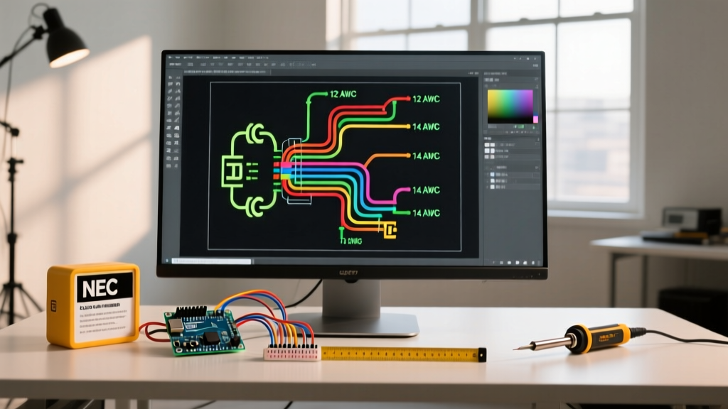
Calculation: 14A × 1.25 = 17.5A. Referencing NEC Table 310.16 (75°C column for standard terminations), a 14 AWG copper wire is rated for 20A. However, for mechanical durability and voltage drop mitigation over long runs, professional panel shops standardize on 12 AWG. Using the AEWIRE command, draw the conductors and assign the wire layer to '480VAC_3PH'. The software will automatically prompt you to label the wire gauge as '12 AWG THHN/THWN-2'.
Component Sizing and AutoCAD Annotation Matrix
| Component | NEC Article | Sizing Rule | AutoCAD Annotation Requirement |
|---|---|---|---|
| Branch Breaker | 430.52 | Max 250% FLA (35A) | Must display Amp rating, pole count, and interrupt rating (e.g., 65kAIC). |
| Branch Conductors | 430.22 | Min 125% FLA (17.5A) | Wire number, gauge (12 AWG), and insulation type (THHN) on schematic. |
| Overload Relay | 430.32 | 115% - 125% Nameplate FLA | Catalog part number must match the exact trip class (e.g., Class 10 or 20). |
| Disconnect Switch | 430.109 | Min 115% FLA (Horsepower rated) | Must include 'HP Rated' text and lockout/tagout (LOTO) identifier. |
5 Fatal Code Violations Hidden in Wiring Diagrams
Even experienced drafters introduce NEC violations into their schematics that translate directly into failed field inspections. Avoid these common pitfalls when generating an electrical wiring diagram in AutoCAD:
- Omitting the Control Circuit Transformer Sizing: If your 480V to 120V control transformer is not sized per NEC 430.72 (which dictates specific overcurrent protection ratios based on transformer VA), the primary fuses will blow during motor inrush. Always annotate the transformer VA rating and primary/secondary fuse sizes directly on the schematic.
- Missing Equipment Grounding Conductor (EGC) Routing: A schematic that only shows phase and neutral conductors is incomplete. NEC Article 250 requires an EGC. Use the
AEWIREcommand with a dedicated green 'GROUND' layer to route the ground wire to the motor starter enclosure and the motor frame, terminating at the PE (Protective Earth) busbar symbol. - Improper Wire Numbering Across Terminals: Wire numbers must change when passing through a terminal block or a spade lug. AutoCAD Electrical handles this via the
AEWIRENOcommand. Failing to segment wire numbers makes troubleshooting impossible for field technicians using a multimeter. - Using IEC Symbols for US Installations: Mixing IEC (International Electrotechnical Commission) rectangular contactor symbols with JIC ladder logic creates ambiguity. Inspectors in the US are trained to read JIC symbols. Mixing standards is a primary cause of rejected submittal packages.
- Ignoring Arc Flash Labeling Callouts: While the NEC focuses on installation, NFPA 70E requires arc flash warning labels. Advanced AutoCAD Electrical workflows now include custom attributes on the main disconnect symbol that automatically pull calculated incident energy data (e.g., 'Cal/cm2') to be printed on physical panel stickers.
Advanced Terminal Strip Layouts for Field Wiring
The schematic is only half the battle; the physical panel layout dictates wire bending space, which is strictly governed by NEC Article 312.6. AutoCAD Electrical’s Terminal Strip Editor (AETERM) allows you to generate a 1:1 scale physical layout of your DIN rail terminal blocks.
By associating the schematic wire numbers with the physical terminal strip layout, the software generates a comprehensive Bill of Materials (BOM) and a From/To wire list. This list is critical for UL 508A panel shops, as it proves to the UL field inspector that the wire routing and terminal assignments match the approved schematic exactly, ensuring no undocumented modifications were made on the shop floor.
Authoritative References and Standards
To maintain compliance and stay updated on code cycles, regularly consult the following authoritative resources:
- National Fire Protection Association (NFPA): Access the latest developments on the NEC (NFPA 70) and electrical standards for industrial machinery (NFPA 79) at the NFPA 70 Standard Development Portal.
- Autodesk Knowledge Network: For specific command syntax, layer management, and database linking in the AutoCAD Electrical toolset, refer to the official AutoCAD Electrical Help Documentation.
- Occupational Safety and Health Administration (OSHA): Review federal mandates regarding electrical safety, lockout/tagout procedures, and wiring design protection at the OSHA Electrical Safety e-Tools page.