
Mastering Hydronic Zoning: The Taco Zone Valve Architecture
Designing a multi-zone hydronic heating system requires more than just piping copper; it demands a flawless low-voltage control strategy. As smart home integration becomes standard in 2026, ensuring your legacy 24VAC hydronic components communicate correctly with modern Wi-Fi thermostats is critical. The foundation of this control network relies on a precise wiring diagram for Taco zone valve configurations. Whether you are retrofitting an older single-zone boiler or planning a new construction radiant floor manifold, understanding the electrical load, end-switch logic, and transformer sizing will prevent system chatter, blown fuses, and premature power head failure.
Core Components: Identifying Your Taco Valve Series
Before drafting your schematic, you must identify the exact Taco zone valve series you are installing. Taco manufactures several distinct lines, each with specific electrical footprints and physical connection methods. Selecting the wrong transformer or misinterpreting the terminal block based on an assumed model is the most common cause of installation failure.
| Model Series | Connection Type | End Switch Included? | Power Rating (VA) | 2026 Avg. Unit Cost |
|---|---|---|---|---|
| Taco 571-2 / 572-2 / 573-2 | Sweat (Copper) | No (2-Wire) | 8 VA | $65 - $85 |
| Taco 571-3 / 572-3 / 573-3 | Sweat (Copper) | Yes (3-Wire) | 8 VA | $85 - $110 |
| Taco 5100 Series (e.g., 5100-2G) | ProPress / Crimp | Varies by suffix | 8 VA | $90 - $120 |
| Taco 5900 Series | Press / Threaded | Yes (Integrated) | 10 VA | $130 - $160 |
The Anatomy of the Wiring Diagram
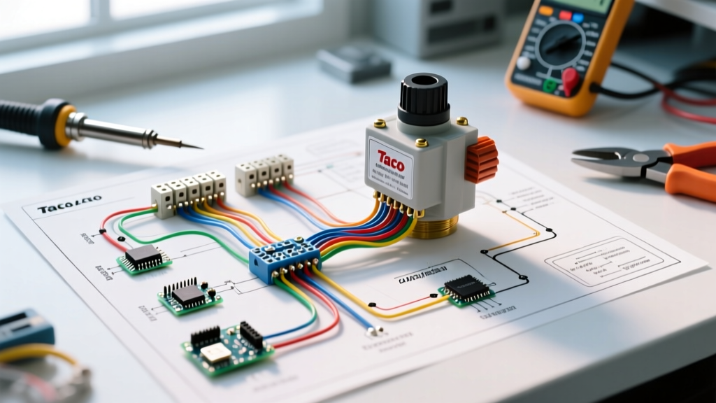
A standard wiring diagram for Taco zone valve systems hinges on the difference between 2-wire and 3-wire configurations. The power head (the black plastic box atop the brass valve body) contains a synchronous motor and, on specific models, a micro-switch.
Terminals 1 & 2: The Motor Circuit
Terminals 1 and 2 supply 24VAC power to the zone valve motor. When the thermostat calls for heat (closing the R and W contacts), it completes the 24VAC circuit. The motor engages, rotating a gear train that slowly opens the brass valve (typically taking 10 to 15 seconds). Note: Polarity does not matter on 24VAC systems; you can wire the hot and common to either Terminal 1 or 2.
Terminals 2 & 3: The End Switch Circuit
Only present on "-3" models (like the Taco 573-3) or specific press-fit models, Terminal 3 is the output side of the internal end switch. The end switch is a mechanical relay that only closes after the valve is 100% open.
- Terminal 2 acts as the common bridge for both the motor and the end switch.
- Terminal 3 sends 24VAC to the boiler aquastat, Taco switching relay (e.g., PC2504), or circulator pump only when the valve is fully open.
Transformer Sizing and Load Calculations
The most critical planning step in your wiring diagram for Taco zone valve layouts is sizing the 24VAC step-down transformer. Undersizing leads to voltage drop, causing the valve motors to hum without opening (stall condition), which eventually burns out the motor windings.
The Inrush Current Trap: A Taco 570 series power head requires approximately 8 VA to operate. However, the inrush current when the motor first engages is significantly higher than the holding current. If you have a 4-zone system and all four thermostats call for heat simultaneously on a cold morning, the transformer must handle the combined inrush load plus the boiler relay coil.
Calculation Framework (4-Zone Example)
- 4x Taco 573-3 Zone Valves @ 8 VA each = 32 VA
- 1x Taco PC2504 Switching Relay = 2 VA
- 1x Honeywell Aquastat / Boiler Control = 3 VA
- Total Steady-State Load: 37 VA
While a standard 40VA transformer (like the Honeywell AT72D1683, priced around $40 in 2026) technically covers the steady-state load, it leaves zero headroom for inrush current or future expansion. Best Practice: Always specify a 50VA or 75VA transformer (e.g., Taco T024075, approx. $55) for systems with 3 or more zones to ensure longevity and prevent blown fuses.
Wire Gauge Selection and Routing Rules
According to guidelines supported by the National Electrical Code (NFPA 70) for Class 2 low-voltage circuits, wire gauge must be selected based on the total run length to prevent voltage drop. Zone valves require a minimum of 20VAC to operate reliably; dropping below this threshold causes the valve to chatter or fail to close.
| Wire Gauge (AWG) | Max Recommended Run Length (One Way) | Application Scenario |
|---|---|---|
| 18 AWG Solid/Stranded | Up to 80 feet | Standard residential single-floor installs |
| 16 AWG Solid/Stranded | 80 to 150 feet | Multi-story homes, long runs to detached garages |
| 14 AWG Solid/Stranded | 150+ feet | Large commercial spaces or expansive radiant driveways |
Pro Tip: Always use 18/3 or 16/3 thermostat wire even for 2-wire zone valves. The unused third wire serves as a critical backup pull in case a wire breaks inside the wall cavity during drywall installation.
Step-by-Step Installation Planning Workflow
- Map the Thermostat Drops: Run 18/3 wire from each thermostat location to a centralized junction box near the boiler manifold.
- Install the Switching Relay: Mount a Taco PC2504 (or equivalent 4-zone relay). This eliminates the need to daisy-chain end switches manually, as the relay board handles the parallel wiring internally.
- Wire the Valves to the Relay: Connect Zone Valve Terminals 1 and 2 to the corresponding "Zone Valve" terminals on the relay board.
- Wire the End Switches: Connect Zone Valve Terminals 2 and 3 to the "End Switch" terminals on the relay board. The relay will automatically aggregate these and send a single 24VAC signal to the boiler's TT (Thermostat) terminals when any zone is satisfied.
- Verify Transformer Polarity: While 24VAC has no strict polarity, maintaining a consistent "Common" (C) and "Hot" (R) mapping across all thermostats and relays prevents short circuits when upgrading to smart thermostats later.
Troubleshooting Matrix: Common Edge Cases
Even with a perfect wiring diagram for Taco zone valve systems, field conditions introduce variables. Use this matrix to diagnose post-installation anomalies.
| Symptom | Probable Cause | Diagnostic Fix |
|---|---|---|
| Valve hums but does not open | Voltage drop below 20VAC or failed capacitor in power head | Measure voltage at Terminals 1 & 2 while calling for heat. If <20V, upgrade wire gauge or transformer. |
| Boiler fires, but circulator doesn't run | End switch stuck open or miswired to relay | Jump Terminals 2 & 3 at the valve. If circulator starts, replace the valve power head. |
| Valve opens, but won't close when heat is satisfied | Thermostat shorting, or manual open lever left engaged | Ensure the manual lever on the Taco valve is flipped to "Auto". Check for crossed R/W wires. |
| Transformer overheats and burns out | Short in the 24VAC field wiring or undersized VA rating | Disconnect all field wires. Test transformer with no load. If it stays cool, hunt for a pinched 18 AWG wire in the walls. |
Authoritative References & Standards
Proper hydronic planning requires adherence to industry standards. For comprehensive specifications on Taco product lines, consult the Taco Comfort Solutions official technical library. For broader context on low-voltage control wiring and safety clearances, refer to the NFPA 70 National Electrical Code, specifically Article 725 covering Class 1, Class 2, and Class 3 remote-control and signaling circuits. Finally, for system efficiency metrics regarding hydronic zoning, review the U.S. Department of Energy's Home Heating Systems guidelines.