
Understanding the Wiring Diagram for a Ceiling Fan
Installing a ceiling fan involves more than just matching colored wires and twisting them together. Unlike standard light fixtures, ceiling fans introduce mechanical vibration, motor inductance, and significant weight to your electrical system. A proper wiring diagram for a ceiling fan must account for both the physical support of the fixture and the precise electrical characteristics of the circuit. Misjudging wire gauge can lead to voltage drop and overheating, while misinterpreting manufacturer color codes is the leading cause of short circuits and tripped breakers in DIY fan installations.
This comprehensive reference guide bridges the gap between the National Electrical Code (NEC) requirements for branch circuits and the proprietary color codes used by major ceiling fan manufacturers like Hunter, Hampton Bay, and Minka-Aire.
Wire Gauge Selection & NM-B Cable Identification
The foundation of any safe ceiling fan installation is verifying that the branch circuit wire gauge matches the overcurrent protection device (breaker) at the main panel. According to National Fire Protection Association (NFPA) NEC Article 334, Nonmetallic-Sheathed Cable (commonly known as Romex or NM-B) must be sized correctly for the circuit's amperage.
Standard Residential Gauge Requirements
- 15-Amp Circuits: Require a minimum of 14 AWG copper wire. The standard NM-B cable used is 14/2 (with ground) or 14/3 (with ground).
- 20-Amp Circuits: Require a minimum of 12 AWG copper wire. The standard NM-B cable used is 12/2 or 12/3.
Expert Insight: While a ceiling fan and light kit combined rarely draw more than 2 to 3 amps (roughly 250-350 watts), you must size the wire to the breaker, not the load. Never install 14 AWG wire on a 20-amp breaker, even if the fan is the only device on the circuit. Furthermore, if the cable run from the panel to the fan exceeds 50 feet, upsizing to 12 AWG on a 15-amp circuit is recommended to mitigate voltage drop, which can cause fan motors to hum or overheat.
NM-B Cable Jacket Color Matrix
Modern NM-B cables use color-coded outer jackets to help electricians and DIYers quickly identify the wire gauge inside without stripping the sheath.
| Jacket Color | Wire Gauge (AWG) | Cable Configuration | Max Breaker Size | Typical Application |
|---|---|---|---|---|
| White | 14 AWG | 14/2 or 14/3 | 15 Amps | Standard lighting & fan circuits |
| Yellow | 12 AWG | 12/2 or 12/3 | 20 Amps | Kitchen/Bath fans, long lighting runs |
| Orange | 10 AWG | 10/2 or 10/3 | 30 Amps | Heavy appliances (Not used for fans) |
Decoding Color Codes: House Wiring vs. Fan Fixture
The most common point of failure when following a wiring diagram for a ceiling fan is the assumption that the wires coming out of the ceiling match the color logic of the wires coming out of the fan motor housing. They do not.
House wiring follows strict NEC color standards, while ceiling fan manufacturers use functional color coding to separate the fan motor from the integrated light kit. Always verify your connections against the matrix below before applying power.
House vs. Fixture Color Code Matrix
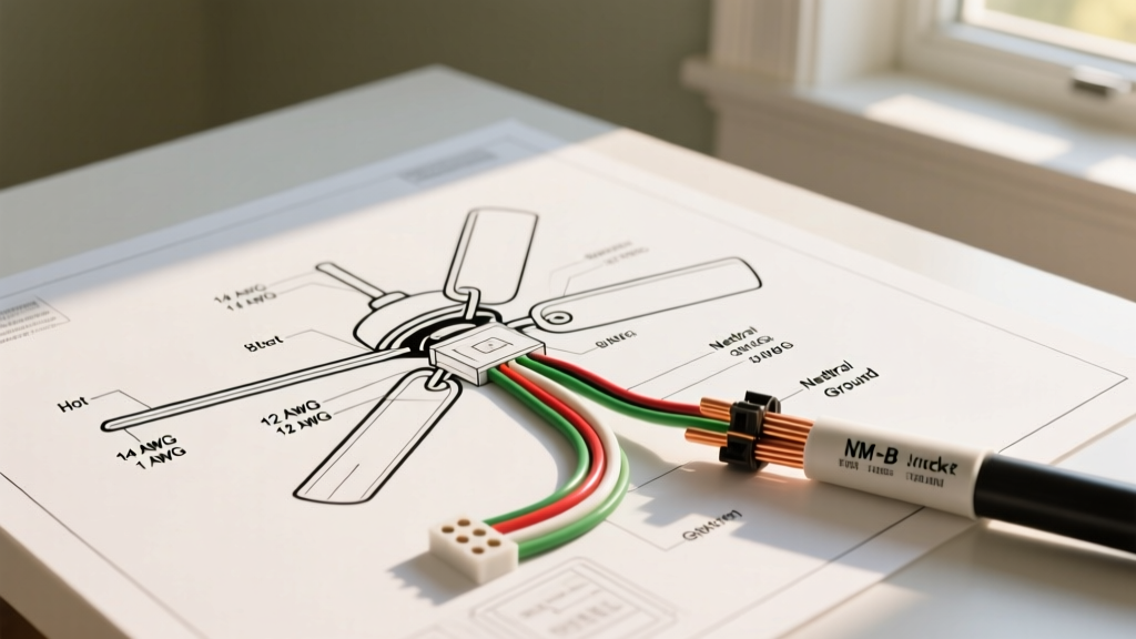
| Wire Function | House Wire Color (NM-B) | Fan Wire Color (Typical) | Connection Notes |
|---|---|---|---|
| Ground | Bare Copper or Green | Green or Green w/ Yellow Stripe | Must connect to the mounting bracket AND the house ground wire. |
| Neutral | White | White | Connect house white to fan white. Do NOT connect to the blue wire. |
| Hot (Fan Motor) | Black | Black | Powers the fan motor. Connects to the switch leg. |
| Hot (Light Kit) | Red (if 3-wire) or Black | Blue | Powers the light fixture. Often confused with a second hot phase. |
Step-by-Step: Single Wall Switch Configuration
In a standard single-switch setup, the wall switch controls both the fan motor and the light kit simultaneously. The fan's internal pull chains are used to adjust speed and toggle the light.
- Verify Power: Turn off the breaker and use a non-contact voltage tester (e.g., Klein Tools NCVT-2) on the ceiling wires to confirm the circuit is dead.
- Prepare the Wires: Strip exactly 3/4 inch of insulation from the NM-B wires using wire strippers like the Klein 11057. Do not nick the copper conductor, which creates a weak point prone to snapping under fan vibration.
- Grounding: Connect the bare copper house ground to the green fan ground and the green grounding screw on the ceiling mounting bracket using a green wire nut.
- Neutral Connection: Twist the white house wire and the white fan wire together. Secure with a tan or blue wire nut (Ideal 341 or Gardner Bender 44-1041).
- Hot Connection (The Bridge): Connect the black house wire (switch leg) to both the black fan wire (motor) and the blue fan wire (light kit). Use a slightly larger wire nut (Ideal 314 Red or yellow SureWire connector) to accommodate three 14 AWG or 12 AWG wires.
- Tug Test & Secure: Gently tug each wire nut to ensure a solid mechanical connection. Fold the wires neatly into the junction box, ensuring no bare copper is exposed outside the nuts.
Advanced Configuration: Dual Switch (Independent Fan & Light)
If your ceiling features a 3-wire cable (14/3 or 12/3, identifiable by the Red wire alongside the Black, White, and Bare wires), you can wire the fan and light to separate wall switches. This is highly recommended for modern smart home integrations.
- House Black Wire: Connects to the Fan's Black wire (Motor).
- House Red Wire: Connects to the Fan's Blue wire (Light Kit).
- House White Wire: Connects to the Fan's White wire (Neutral).
- House Bare Wire: Connects to the Fan's Green wire (Ground).
Note: At the wall switch box, the black and red wires will act as separate switch legs returning from the dual-gang switch up to the ceiling canopy.
Critical Edge Cases & Troubleshooting
1. The "Humming" Motor Issue (Dimmer Switch Incompatibility)
If your newly wired ceiling fan emits a loud humming noise or runs erratically, check your wall switch. Standard incandescent dimmer switches use TRIAC phase-cutting, which destroys the sine wave required by AC induction motors. This causes severe overheating and can lead to a fire. Solution: Replace the standard dimmer with a fan-rated speed control module, such as the Lutron MACL-LFQ (approx. $40) or Leviton RNL06, which are specifically engineered to handle inductive motor loads.
2. Missing Ground Wire in Older Homes
Homes built before the 1960s often feature ungrounded knob-and-tube or early cloth-sheathed wiring. According to Underwriters Laboratories (UL) and NEC Article 409.18, ceiling fans must be grounded due to their metal housings and vibration. If no ground is present at the ceiling box, you cannot simply cap the green wire and ignore it. You must either pull a new 14/2 NM-B cable with a ground from the panel, or install a GFCI breaker at the panel and label the fan box "GFCI Protected, No Equipment Ground" (though pulling a new ground is the only code-compliant method for new fan installations in most jurisdictions).
3. Junction Box Weight Ratings
Electrical wiring is only half the battle. A standard plastic ceiling junction box is only rated to hold 35 pounds. Many modern flush-mount and large-blade ceiling fans exceed 40 pounds. If your fan is heavy, you must retrofit the ceiling with a fan-rated brace and box, such as the Raco 283 Heavy-Duty Fan Box or the Madison Electric MPRBRFZ adjustable brace, which secures directly to the ceiling joists to handle the dynamic torque of the spinning motor.
Final Safety Verification
Before attaching the fan canopy and installing the light bulbs, double-check that no wire nut connections are pushed so deeply into the junction box that they are pinched by the mounting bracket screws. Once the canopy is secured, restore power at the breaker and test the pull chains and wall switches independently. Proper adherence to wire gauge limits and precise color-code matching ensures your ceiling fan will operate safely and quietly for decades.