
Decoding the Wiring Diagram for a Generator and ATS Setup
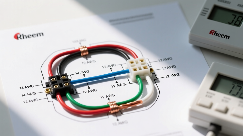
Integrating a standby generator into your home electrical system requires more than just running heavy-gauge wire from the pad to the house. The true nerve center of any backup power system is the Automatic Transfer Switch (ATS) and its integration with your main breaker panel. Understanding the wiring diagram for a generator and ATS is critical to ensuring seamless power transitions, protecting utility workers from backfeed, and complying with the latest 2026 National Electrical Code (NEC) standards.
In this comprehensive panel and breaker guide, we will dissect the exact wiring architecture for a standard 200-amp residential setup, utilizing the highly popular Generac Guardian 22kW (Model 7077) paired with a Generac 200-Amp Service Entry Rated ATS (Model 99510). Whether you are an electrical apprentice, a seasoned journeyman verifying a schematic, or a highly skilled DIYer preparing for an inspection, this guide provides the granular technical data you need.
Transfer Switch vs. Generator Interlock Kit: A Technical Comparison
Before diving into the schematic, it is vital to understand why an ATS is the preferred choice for whole-home backup over a manual interlock. While interlock kits are cheaper, they lack the automated intelligence and utility-isolation reliability required for modern smart homes.
| Feature | Automatic Transfer Switch (ATS) | Generator Interlock Kit |
|---|---|---|
| Avg. Hardware Cost (2026) | $850 - $1,400 | $85 - $150 |
| Switching Mechanism | Motorized, double-throw, break-before-make | Manual physical slider on main/breaker |
| Utility Isolation |