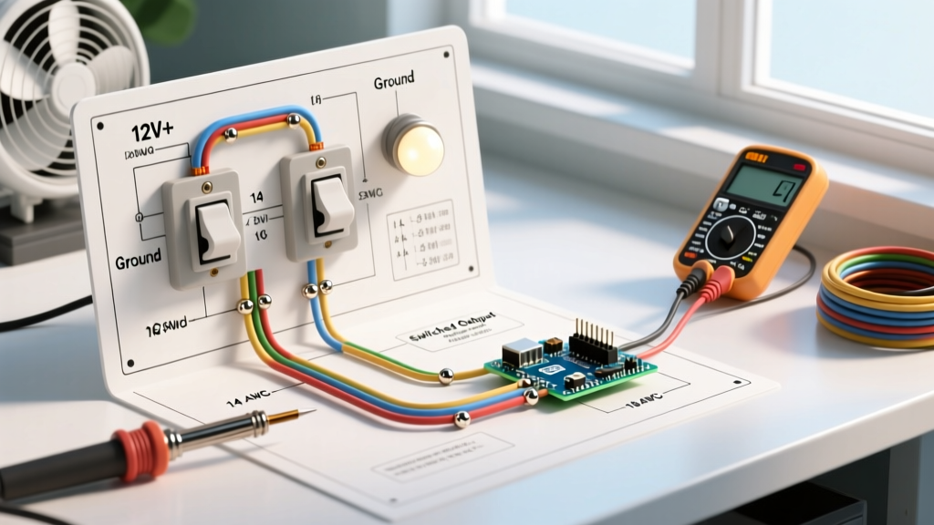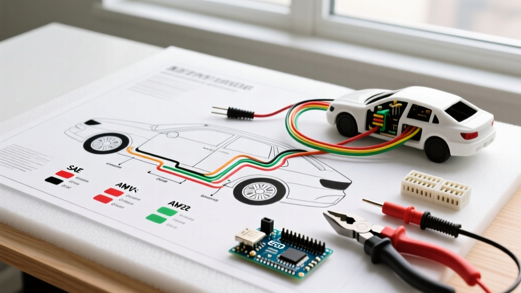

Why a Single Electric Fan Relay Wiring Diagram is Critical for Safety
When integrating high-amperage cooling systems into vehicles, off-road rigs, or custom HVAC setups, relying on a direct switch connection is a severe fire hazard. A standard 16-inch SPAL or Derale electric cooling fan draws between 18A and 25A during continuous operation, but can spike to 40A during inrush (startup). Routing this current through a standard dashboard toggle switch or an engine control unit (ECU) pin will inevitably melt the wiring harness or destroy the silicon driver. This is where a proper single electric fan relay wiring diagram becomes non-negotiable.
By utilizing a standard ISO mini relay (often referred to as a Bosch-style 4-pin or 5-pin relay), you isolate the high-current load path from the low-current control circuit. In 2026, with vehicle electrical systems becoming increasingly complex and sensitive to voltage spikes, adhering to strict safety and code compliance protocols is the only way to ensure long-term reliability and prevent catastrophic electrical fires.
Anatomy of the Standard ISO Mini Relay
Before cutting a single wire, you must understand the terminal designations on a standard 4-pin automotive relay. The industry standard follows the DIN 72552 numbering system:
- Pin 30 (Common): The high-current power input. This connects directly to the vehicle battery via a primary fuse.
- Pin 87 (Normally Open): The high-current output. This routes power directly to the electric fan motor when the relay is energized.
- Pin 85 (Coil Ground): The low-current ground path for the internal electromagnetic coil.
- Pin 86 (Coil Trigger): The low-current 12V trigger input. This connects to your thermostat switch, ECU, or dashboard toggle switch.
Safety Warning: Never use Pin 87a (the Normally Closed terminal on 5-pin relays) for a cooling fan circuit. If the relay fails or is removed, Pin 87a will continuously power the fan, draining your battery and potentially causing the motor to overheat without the engine running.
Wire Gauge, Amperage, and Overcurrent Protection Matrix
The most common failure point in DIY fan wiring is undersized conductors. According to the SAE J1128 Standard for Low Tension Primary Cable, automotive wire must be rated for high-temperature engine bay environments. Standard PVC household wire (THHN) will melt and short-circuit under hood temperatures exceeding 125°C. Always use cross-linked polyethylene (XLPE) insulated wire, specifically GXL or TXL grade.
Below is the definitive compliance matrix for sizing your conductors and overcurrent protection based on the fan's maximum continuous draw. Note that fuse sizing must protect the wire, not the load.
| Fan Max Continuous Draw | SAE J1128 Wire Gauge (GXL) | Primary Fuse Type & Size | Recommended Relay Rating |
|---|---|---|---|
| Up to 15 Amps | 14 AWG | 20A ATO/ATC Blade | 30A Standard ISO |
| 16 to 25 Amps | 10 AWG | 30A Maxi Blade | 40A Heavy Duty ISO |
| 26 to 40 Amps | 8 AWG | 50A MIDI / AME | 60A High-Current (HCV) |
| 41 to 60 Amps (Dual Fans) | 4 AWG | 80A MEGA / AMI | Dual 40A Relays Required |
Code Compliance: SAE and NEC Standards for Mobile DC
While the NFPA 70 (National Electrical Code) primarily governs AC building wiring, its principles regarding overcurrent protection (Article 240) and conductor ampacity (Article 310) heavily influence mobile DC standards adopted by the American Boat & Yacht Council (ABYC) and SAE. For your single electric fan relay wiring diagram, you must adhere to the following three code-derived rules:
1. The 18-Inch Fuse Rule
The primary high-current fuse (connected to Pin 30) must be located within 18 inches of the power source (the battery positive terminal). If a short circuit occurs between the battery and the relay, this fuse is the only thing preventing the main power wire from becoming a glowing heating element that ignites the vehicle's interior.
2. Dedicated Grounding Architecture
Do not rely on the vehicle's painted or powder-coated chassis for the relay coil ground (Pin 85). Modern vehicles use extensive anti-corrosion coatings that create high-resistance ground paths. Run a dedicated 14 AWG ground wire from Pin 85 directly to a clean, bare-metal grounding bus bar bolted to the engine block or chassis.
3. Voltage Drop and Thermal Runaway
Electric motors are constant-power devices. If your wire gauge is too small, voltage drops across the harness. A fan designed for 13.8V receiving only 11.5V will draw more current to compensate for the lost voltage, leading to thermal runaway and melted connectors. Keep total circuit voltage drop below 3% (0.36V on a 12V system).
The Hidden Danger: Flyback Voltage and ECU Protection
This is the most critical edge case in modern single electric fan relay wiring diagrams. An electromagnetic relay coil is an inductor. When the low-current trigger (Pin 86) is switched off, the magnetic field collapses rapidly. According to Faraday's Law of Induction, this generates a massive reverse-voltage spike (flyback voltage) that can easily exceed 100V.
If your fan relay is triggered directly by an aftermarket ECU (such as a Holley Terminator X, MegaSquirt, or Haltech) or a delicate PWM fan controller, this 100V spike will instantly blow the ECU's internal low-side driver transistor, resulting in a $500 to $1,500 replacement bill.
The Solution: You must suppress the flyback voltage. You have two options:
- External Diode: Solder a standard 1N4004 rectifier diode across the relay's Pin 85 and Pin 86. The cathode (the silver stripe on the diode) must point toward Pin 86 (the 12V trigger source). This creates a recirculation loop that safely absorbs the voltage spike.
- Internal Suppression Relay: Purchase a relay with a built-in suppression resistor or diode. The Littelfuse HWF series or Bosch 0332014150 (with internal diode) are industry standards in 2026, typically costing between $6 and $12 each. Avoid $2 no-name relays from bulk online marketplaces, as they lack internal suppression and use inferior copper-alloy contacts that pit and weld shut over time.
Step-by-Step Safe Installation Protocol
To ensure your wiring diagram translates into a safe, physical installation, follow this professional workflow:
- Disconnect the Battery: Always isolate the negative terminal before cutting or crimping any wires. Use a memory saver plugged into the OBD-II port if your vehicle requires ECU relearn procedures.
- Mount the Relay in a Dry Zone: Engine bays are wet environments. If the relay is mounted below the radiator shroud or near the frame rails, use an IP67-rated sealed relay and a sealed fuse holder. Standard ISO relays will corrode internally within six months if exposed to road spray.
- Crimp, Do Not Solder: Solder creates a rigid joint that will fracture under the high-frequency vibrations of a vehicle chassis. Use a ratcheting crimper (such as the IWISS SN-28B or Glarks SN-48B) with non-insulated open-barrel terminals, followed by adhesive-lined heat shrink.
- Use Adhesive-Lined Heat Shrink: Standard PVC electrical tape degrades and unravels in engine bay heat. Use 3M EPS300 or TE Connectivity Raychem adhesive-lined heat shrink (minimum 3:1 shrink ratio). When heated, the internal meltable adhesive flows into the wire strands, creating a completely waterproof, strain-relieved seal.
- Route Wires Separately: Keep the high-current fan wires (Pins 30 and 87) physically separated from low-current sensor wires or ECU trigger wires to prevent Electromagnetic Interference (EMI) from inducing noise into sensitive data lines.
Common Failure Modes and Troubleshooting
Even with a perfect single electric fan relay wiring diagram, physical degradation can cause failures. Here is how to diagnose the most common issues:
- Relay Chattering (Rapid Clicking): This occurs when the trigger voltage is marginal (usually below 9V). Check the thermostat switch or ECU output for voltage drop. A failing alternator or a weak battery can also cause the relay to drop out as the fan's inrush current pulls the system voltage down.
- Contacts Welding Shut: If the fan continues to run after the ignition is turned off and the trigger is removed, the internal copper contacts have welded together due to arcing during the 40A inrush phase. Immediate action: Pull the primary Maxi fuse to stop the fan, then replace the relay with a higher-amperage rated unit (e.g., upgrade from a 30A to a 50A relay).
- Melted Spade Connectors: If the female spade connectors on the relay harness are discolored or melted, they lack sufficient spring tension. Standard stamped brass connectors lose tension after repeated heat cycles. Upgrade to beryllium-copper or phosphor-bronze high-tension terminals to maintain a zero-resistance connection.
Final Thoughts on System Integrity
Executing a safe single electric fan relay wiring diagram requires looking beyond basic continuity. By respecting SAE wire standards, enforcing strict overcurrent protection placement, and mitigating inductive flyback voltage, you protect both your vehicle's electrical infrastructure and its occupants. In high-current mobile applications, the cost of premium components like adhesive heat shrink, ratcheting crimpers, and suppressed relays is a fraction of the cost of a harness fire. Always test your completed circuit with a digital multimeter to verify voltage drop at the fan motor under load, ensuring your system is ready for the demands of the road.