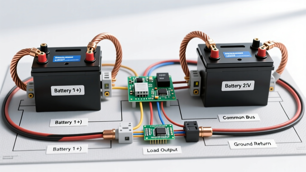

Master Wiring Diagram for 2 Boat Batteries: Topology Breakdown
Designing a reliable marine electrical system requires strict separation between engine-cranking demands and house appliance loads. A single-bank system risks stranding you at the anchorage if a 12V compressor fridge or windlass drains the battery overnight. By implementing a dedicated wiring diagram for 2 boat batteries, you create a fail-safe architecture: Bank 1 (Starting) is reserved exclusively for the engine, while Bank 2 (House) powers your navigation, lighting, and galley appliances.
This comprehensive appliance wiring tutorial details the exact topology, component selection, and American Boat & Yacht Council (ABYC) compliance standards required to build a dual-bank system in 2026. Whether you are outfitting a 24-foot center console or a 40-foot cruising sailboat, the principles of isolation, fusing, and voltage drop management remain universal.
Core Components for a Dual-Bank Marine System
Before running a single foot of marine-grade tinned copper wire, you must procure the correct isolation and circuit protection hardware. Avoid outdated diode-based battery isolators, which introduce a 0.6V to 1.0V drop that severely undercharges the house bank.
1. Automatic Charging Relay (ACR)
The cornerstone of modern dual-battery wiring is the ACR. We recommend the Blue Sea Systems 7650 ACR (rated for 120A continuous). Unlike manual 1-2-BOTH switches, an ACR automatically combines the banks when it senses a charging voltage (typically 13.7V) from the alternator or shore charger, and isolates them when the voltage drops below 12.75V. As of 2026, expect to pay between $140 and $160 for this unit.
2. Busbars and Circuit Protection
Never daisy-chain appliance wires directly to battery terminals. Use Blue Sea Systems 250A BusBars (Model 2107) to distribute power. For main bank protection, Class T fuses are mandatory due to their high Ampere Interrupting Capacity (AIC), which safely halts catastrophic short circuits that standard ANL or AGU fuses cannot handle.
Step-by-Step Wiring Topology
Follow this exact sequence to wire your two boat batteries and connected appliances safely. For full regulatory context, always cross-reference your build with ABYC E-11 AC & DC Electrical Systems Standards.
Step 1: Main Battery Fusing
Within 7 inches of the positive terminal on both batteries, install a Class T fuse block. For a standard 100Ah AGM house bank and a Group 31 starting bank, use a 250A Class T fuse (e.g., Blue Sea 5191). This protects the primary 2/0 AWG feed cables running to your main distribution busbars.
Step 2: The ACR Branch Circuit
The ACR must be fused on both sides. Run 1/0 AWG wire from the load side of Battery 1's main fuse to a 150A ANL fuse, then to the ACR's 'A' terminal. Repeat from Battery 2's main fuse to another 150A ANL fuse, then to the ACR's 'B' terminal. The ACR's ground and sense wires should be 10 AWG, terminated at a dedicated negative busbar and the ignition switch (to prevent the ACR from combining banks while the starter is cranking, which causes voltage spikes).
Step 3: Wiring the House Appliance Panel
From the House Bank positive busbar, feed a Blue Sea ST Blade 12-Circuit Fuse Panel. This panel will serve your interior appliances. Use 6 AWG wire for the panel feed if the run is under 10 feet, protected by a 100A circuit breaker.
Appliance-Specific Wiring Rules
Not all appliances should be wired to the main house fuse panel. High-draw and safety-critical devices require dedicated circuits to prevent voltage drop and ensure operation when the main house switch is off.
Critical Safety Rule: Bilge pumps and fire suppression systems must never be wired through a main battery switch or standard fuse panel. They must be connected directly to the house battery positive terminal via an inline waterproof fuse holder, ensuring they operate even if the main DC panel is switched off or suffers a catastrophic failure.
Wiring 12V Compressor Fridges
Marine fridges, like the Dometic CRX50, are highly sensitive to voltage drop. If the voltage at the compressor terminals drops below 10.5V during the startup surge (which can briefly pull 15A), the unit will trigger a low-voltage cutout and shut down.
- Wire Size: Use 10 AWG for runs up to 15 feet (round trip). For longer runs, step up to 8 AWG.
- Fusing: 15A blade fuse at the panel, plus a dedicated 15A inline fuse near the battery if wired direct.
Wiring Electric Windlasses
A windlass can draw 80A to 120A under heavy load. It must not be wired to the standard house fuse panel.
- Topology: Run 2/0 AWG duplex cable directly from the house bank busbars to a dedicated heavy-duty solenoid (e.g., Blue Sea 400A Continuous Solenoid) mounted near the bow.
- Protection: Install a 150A ANL fuse within 7 inches of the positive busbar connection.
- Control Circuit: Use 12 AWG wire for the helm up/down switches, triggering the solenoid coil.
Wire Gauge & Fusing Matrix
Proper wire sizing is dictated by the maximum continuous load and the total round-trip cable length (positive + negative). The table below provides baseline specifications for a standard 12V dual-bank system assuming a 3% voltage drop limit for critical appliances.
| Circuit / Appliance | Max Continuous Amps | Wire Gauge (Up to 15ft RT) | Wire Gauge (15-25ft RT) | Recommended Fuse |
|---|---|---|---|---|
| Main Bank to Busbar | 250A | 2/0 AWG | 4/0 AWG | 250A Class T |
| ACR Interconnect | 120A | 1/0 AWG | 2/0 AWG | 150A ANL (x2) |
| House Panel Feed | 100A | 4 AWG | 2 AWG | 100A Circuit Breaker |
| Windlass Motor | 110A | 2/0 AWG | 4/0 AWG | 150A ANL |
| 12V Compressor Fridge | 8A (15A Surge) | 12 AWG | 10 AWG | 15A Blade |
| VHF Radio / AIS | 6A | 14 AWG | 12 AWG | 10A Blade |
Note: Always consult the West Marine Wire Size Advisor or ABYC tables for exact calculations based on your vessel's specific cable routing and ambient engine room temperatures.
The Lithium Edge Case: Mixing LiFePO4 and AGM
In 2026, many boaters are upgrading their house bank to Lithium Iron Phosphate (LiFePO4) while retaining a lead-acid or AGM starting bank due to cranking amp reliability in freezing temperatures. You cannot use a standard ACR to connect a LiFePO4 house bank to an AGM starting bank.
Why Standard ACRs Fail with Lithium
LiFePO4 batteries maintain a resting voltage of 13.3V to 13.4V, which is high enough to trick a standard voltage-sensitive ACR into permanently combining the banks. This forces the alternator to charge the lithium bank directly, which can overheat the alternator's diodes and cause the lithium Battery Management System (BMS) to trip into protective shutdown due to unregulated voltage spikes.
The Solution: DC-DC Battery Chargers
Replace the ACR with a Victron Orion-Tr Smart 12/12-30 DC-DC Charger (approx. $260).
- Wire the Orion's input to the Starting Bank (post-fuse).
- Wire the Orion's output to the LiFePO4 House Bank.
- Configure the Orion via Bluetooth to the exact LiFePO4 absorption and float profiles.
Common Failure Modes & Troubleshooting
Even with a perfect wiring diagram for 2 boat batteries, poor execution leads to frustrating failures on the water. Watch for these specific edge cases:
- ACR Chattering: If you hear the ACR rapidly clicking on and off while idling, your alternator output is marginal, or you have severe voltage drop on the 10 AWG sense wires. Clean the sense wire crimps and verify the alternator is outputting at least 13.8V.
- Corroded Busbar Studs: Mixing dissimilar metals (e.g., copper lugs on stainless steel studs without antioxidant paste) causes galvanic corrosion. Always coat all busbar connections with Noalox or marine-grade dielectric grease.
- Undersized Negative Returns: Many DIYers run heavy positive cables but use the engine block or hull bonding for negative returns. ABYC requires a dedicated negative busbar and a negative cable equal in gauge to the positive feed for every major appliance.
Final Inspection & Maintenance
Before energizing the system, perform a continuity test with a multimeter to ensure no accidental grounds exist between the positive busbars and the hull. Once powered, use a thermal camera or an infrared thermometer to scan all crimp connections and fuse blocks after running a heavy load (like the windlass or microwave inverter) for 5 minutes. Any connection reading more than 15°F above ambient temperature indicates a poor crimp or undersized lug that requires immediate remediation.
For further reading on marine circuit protection and high-AIC fuse requirements, review the technical bulletins provided by Blue Sea Systems Circuit Protection. A meticulously wired dual-bank system not only protects your expensive marine appliances but ensures you always have the cranking amps necessary to start your engine and return to port safely.