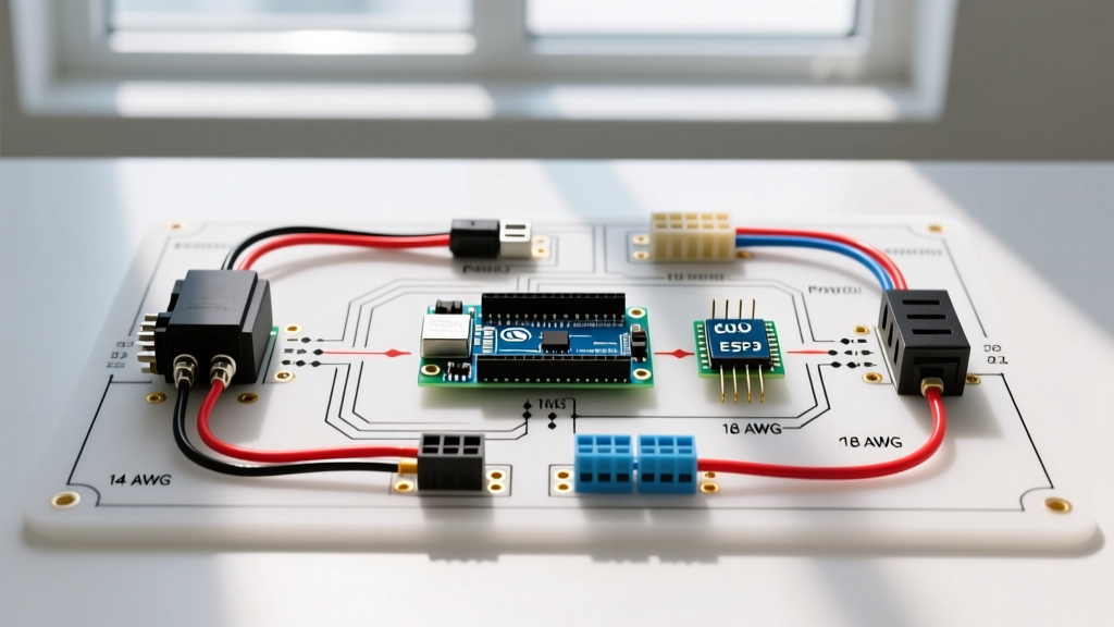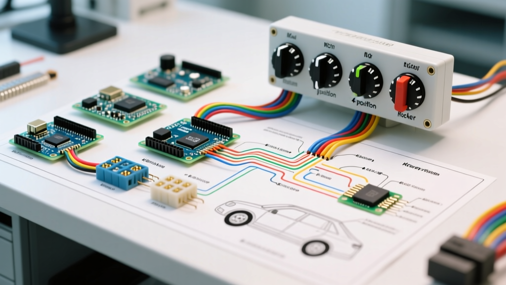

Clarifying the 'Four Way Switch' in Vehicle Systems
When automotive DIYers and RV builders search for a wiring diagram for four way switch configurations, they are usually bridging a terminology gap. In residential AC wiring, a 4-way switch sits between two 3-way switches to control a light from three or more locations. However, in 12V and 24V DC vehicle applications—ranging from overland builds and heavy-duty trucks to marine vessels—a 'four way switch' almost exclusively refers to one of two components:
- 4-Position (4-Way) Rotary Battery Switch: Used for dual-battery isolation (Positions: 1, 2, Both, Off).
- 4-Gang (4-Way) Rocker Switch Panel: A dash-mounted hub controlling four separate auxiliary circuits (e.g., light bars, winches, fridges).
This 2026 vehicle-specific guide provides the exact wiring diagrams, terminal pinouts, and SAE-compliant wire gauge matrices for both interpretations, ensuring your build is safe, efficient, and road-ready.
Diagram 1: 4-Position Dual Battery Isolator (Rotary Switch)
The most critical 4-way switch in any overland or RV build is the heavy-duty battery disconnect and isolator. The industry standard for this is the Blue Sea Systems e-Series 9001E or the Cole Hersee 75920 Master Disconnect. These switches handle up to 350A continuous and feature four distinct positions.
Terminal Layout and Wiring Flow
Unlike residential switches that use 'traveler' wires, a vehicle 4-position rotary switch uses heavy-gauge lugs. Here is the step-by-step wiring sequence for a dual-battery setup:
- Common (C) Terminal: Connects to the main starter motor and the vehicle's primary DC fuse block. Use 1/0 AWG marine-grade tinned copper wire.
- Terminal 1: Connects directly to the positive post of the Cranking (Start) Battery.
- Terminal 2: Connects directly to the positive post of the House (Auxiliary) Battery.
- Ground/Alternator Field: Some advanced 4-way switches include an Alternator Field Disconnect (AFD) terminal to prevent diode blowout if the switch is accidentally turned to 'Off' while the engine is running.
CRITICAL 2026 SAFETY WARNING: Never switch a standard 4-way rotary isolator to the 'Off' position while the alternator is charging. The sudden loss of battery resistance will cause a voltage spike that will instantly destroy your alternator's internal diodes. Always use a switch with an integrated AFD or an automatic Alternator Protection Device (APD).
Diagram 2: 4-Gang Auxiliary Rocker Switch Panel
If your search for a wiring diagram for four way switch setups was aimed at controlling auxiliary accessories, you are likely wiring a 4-gang rocker switch panel (such as the popular Nilight or Auxbeam 4-gang kits). These panels consolidate four separate SPST (Single Pole Single Throw) switches into one dashboard-mounted pod.
The 5-Pin Automotive Relay Pinout
Each of the four switches on the panel triggers a standard 12V 40A automotive relay. Understanding the DIN 72552 relay pinout is mandatory for customizing your harness rather than relying on the fragile plug-and-play jumper wires included in budget kits.
| Relay Pin | Function | Wire Gauge (SAE) | Connection Point |
|---|---|---|---|
| Pin 30 | Common Input (Power) | 12 AWG or 10 AWG | Fused 12V+ from Battery Busbar |
| Pin 87 | Normally Open (Output) | 12 AWG or 14 AWG | Positive lead to Auxiliary Load (e.g., LED Light Bar) |
| Pin 86 | Coil Positive (Trigger) | 16 AWG or 18 AWG | Output from the 4-Way Rocker Switch Panel |
| Pin 85 | Coil Negative (Ground) | 16 AWG or 18 AWG | Chassis Ground or Negative Busbar |
| Pin 87a | Normally Closed | N/A | Unused in standard aux lighting setups (tape off) |
Upgrading the Factory Harness
Most off-the-shelf 4-way switch panels use undersized 16 AWG wire for the main power feeds, which is a fire hazard if you are pulling 30A+ per circuit. In 2026, best practice dictates cutting the factory plug-and-play relay harness. Crimp your own Pin 30 and Pin 87 connections using 12 AWG TXL cross-linked automotive wire and sealed heat-shrink ring terminals. Route the trigger wires (Pins 85/86) through a single firewall grommet to keep the engine bay clean.
Vehicle Wire Gauge Selection Matrix (2026 SAE Standards)
Whether you are wiring the heavy lugs on a 4-position battery switch or the trigger wires on a 4-gang rocker panel, voltage drop is the enemy of 12V DC systems. The following matrix is based on SAE J1128 standards for low-tension primary cable, assuming a 3% maximum voltage drop at 12V nominal.
| Wire Gauge (AWG) | Max Amperage (Chassis) | Max Amperage (Bundle/Conduit) | Max Length for 15A Load (12V) |
|---|---|---|---|
| 1/0 AWG | 350A | 250A | N/A (Battery/Starter runs) |
| 4 AWG | 150A | 120A | N/A (Inverter/Winch runs) |
| 10 AWG | 50A | 30A | 22 Feet |
| 12 AWG | 35A | 20A | 14 Feet |
| 16 AWG | 15A | 10A | 8 Feet |
Troubleshooting Common 4-Way Switch Failures
Even with a perfect wiring diagram for four way switch layouts, environmental factors in vehicles cause unique failure modes. Here is how to diagnose the most common issues:
1. Thermal Runaway at the Common Terminal
Symptom: The main lug on your 4-position rotary switch melts or smells like burning plastic after running the winch or inverter.
Cause: Micro-arcing due to an improperly crimped lug or a loose set screw. In high-amperage DC circuits, a loose connection increases resistance, generating massive heat.
Fix: Cut back the wire, strip it fresh, and use a hydraulic crimper for 1/0 AWG lugs. Apply a layer of dielectric grease over the terminal to prevent galvanic corrosion, and torque the nut to the manufacturer's spec (usually 120-150 in-lbs for 3/8-inch studs).
2. Rocker Switch LED Backlights Flickering
Symptom: The indicator LEDs on your 4-gang dash panel flicker when the engine is idling but stabilize at higher RPMs.
Cause: The switch panel is wired to a switched ignition source that suffers from severe voltage drop, or the vehicle's alternator ripple current is interfering with the LED drivers.
Fix: Move the panel's main 12V+ trigger feed directly to an auxiliary fuse block powered by a clean, heavy-gauge relay from the battery, rather than tapping into the factory cigarette lighter or dash harness.
Expert References and Standards
When designing complex 12V/24V DC systems, always cross-reference your wiring diagrams with established industry standards. For marine and RV crossover builds, the American Boat & Yacht Council (ABYC) E-11 standard provides the most rigorous guidelines for DC overcurrent protection and switch sizing. For heavy-duty truck applications, consult Littelfuse (Cole Hersee) technical bulletins on master battery disconnects. Finally, ensure your wire selection meets SAE International J1128 specifications for under-hood temperature resistance.